KE2010.Instruction Manual.Ver.2.01,Rev.08.pdf - 第550页
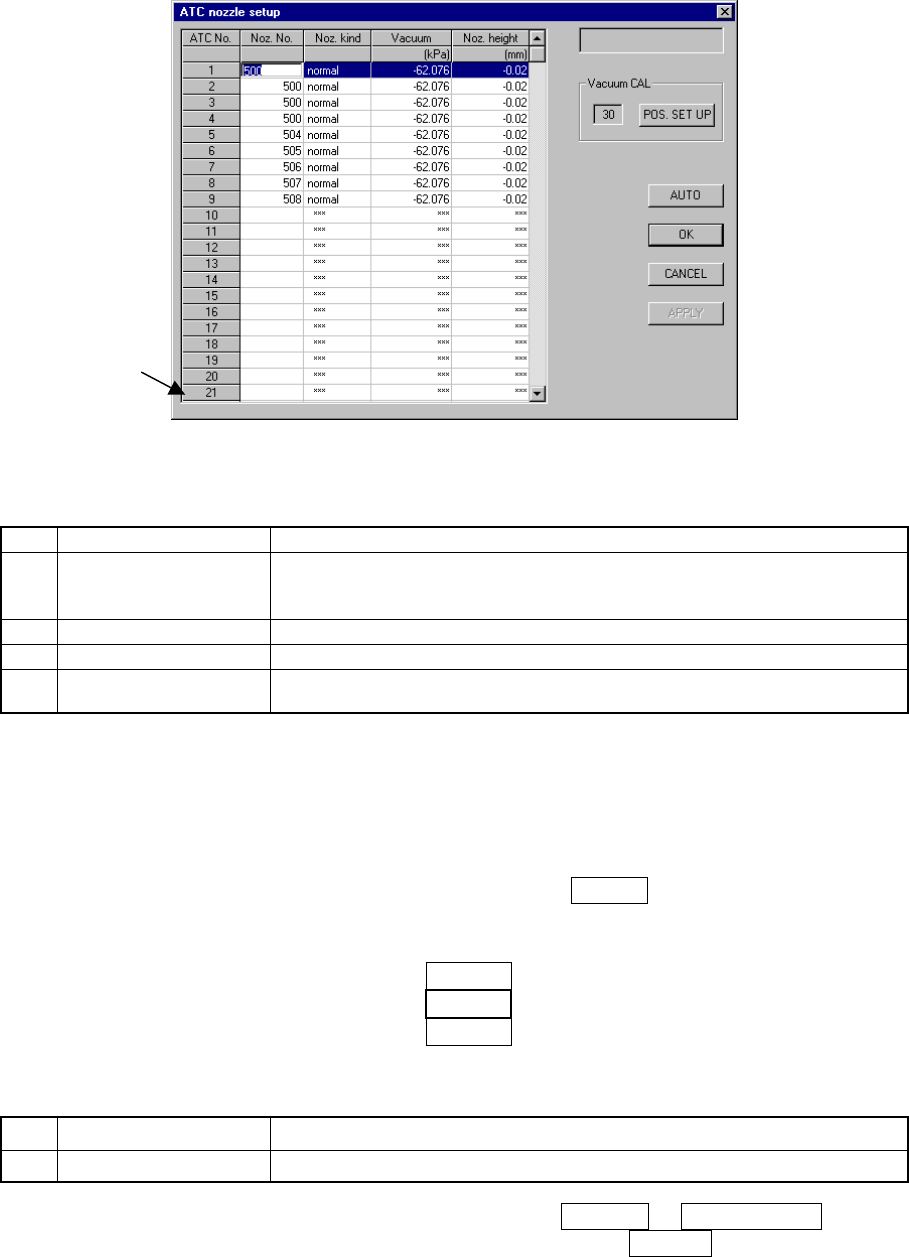
7 − 13 7.2.2.1 A TC nozzle setup W hen [A TC nozzle setup] is selected fr om the [Set ting G roup] menu, the dialog box shown in Figure 7.2.2. 1.1 “A T C nozzle setup” appears. Figure 7.2.2. 1.1 A TC nozzle setup dialog …
7 − 12
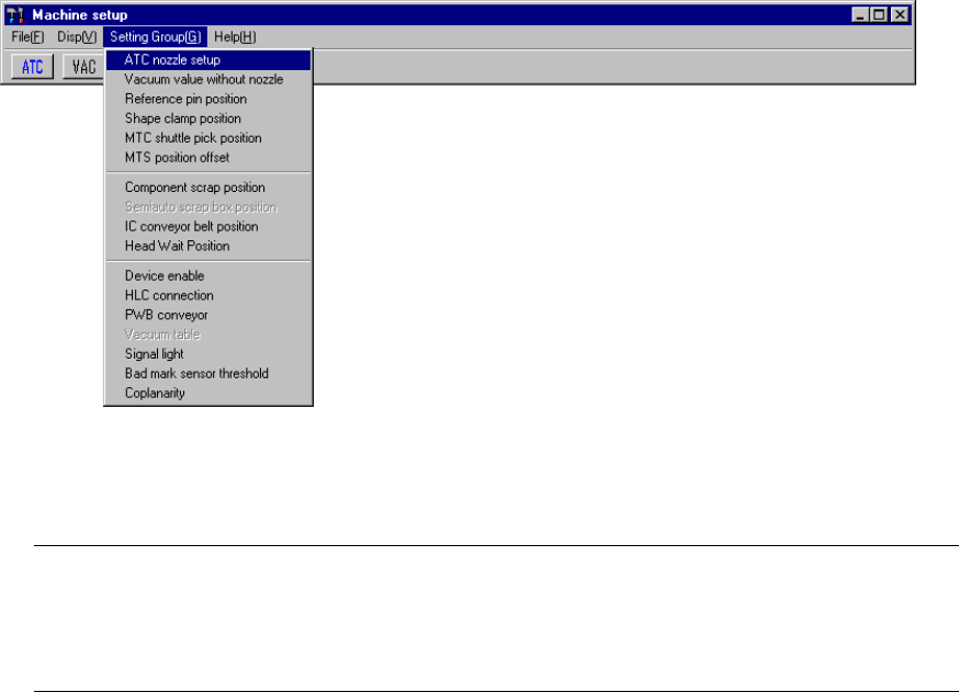
7.2.2 Setting group commands
When you select the [Setting Group] command on the menu bar, the commands
shown in Figure 7.2.2.1 appears on the screen.
Figure 7.2.2.1 Setting Group command items
Note: 1) You cannot select any dimmed menu item. (The displayed available
depending on the model you use )
2) If you have to drive any mechanical part at setup, see Section 7.3
"Mechanical Setup" to drive it.
7 − 13
7.2.2.1 ATC nozzle setup
When [ATC nozzle setup] is selected from the [Setting Group] menu, the dialog box
shown in Figure 7.2.2.1.1 “ATC nozzle setup” appears.
Figure 7.2.2.1.1 ATC nozzle setup dialog box (Screen example when a KE-2020 is used)
(1) Setting items
No. Item Description
1 Nozzle No. Nozzle number to be allocated to an ATC
*1 The displayed available ATC numbers vary depending on the model you
use (see No. 1 “ATC nozzle setup” of Table 7.1.1).
2 Noz. kind Nozzle type to be allocated to an ATC
3 Vacuum Vacuum value with the nozzle attached (for automatic operation only)
4 Noz. height Offset of length with respect to the reference nozzle (for automatic operation
only)
(2) How to set
① Setting the Nozzle No.
− A number is assigned to an ATC. Define a nozzle for each ATC by
using the nozzle number.
− The nozzle number at which the input focus is located can be set. The
numbers entered are validated by the ENTER key or the field selection
key.
Example: (KE-2020)
1 501
2 502 The ATC number "2" can be set.
3 503
− The nozzle number within the range shown in the table below can be entered.
Table 7.2.2.1.1 Setting range of the nozzle number
No. Input item Setting range
1 Nozzle No. 500 to 999 and Space (for no assignment)
− If a number entered is erased by the DELETE or BACK SPACE key,
then that action is validated by pressing the ENTER or field selection
key, the assigned number is canceled and all the setting values shown
disappear
*1
7 − 14
② Noz. kind
− Set the type of a nozzle to be mounted.
− This item is set automatically with the machine only.
However, you have to set the setting item “VacUnit” on the “Vacuum
CAL unit position” dialog box as shown at ⑤ below.
− Available nozzle types are shown in the table below:
Table 7.2.2.1.2 Available nozzle types
No. Setting item Description
1 normal Normal nozzle
2 T-type Cleaner type nozzle
3 Gripper Gripper nozzle
4 VacUnit Vacuum calibration unit
③ Setting the vacuum value: Vacuum
− Set the vacuum value when a nozzle is mounted.
− Only automatic setting is available.
④ Setting the nozzle height: Noz. height
− Set the offset value of the mounted nozzle with respect to the reference
nozzle.
− Only automatic setting is available.
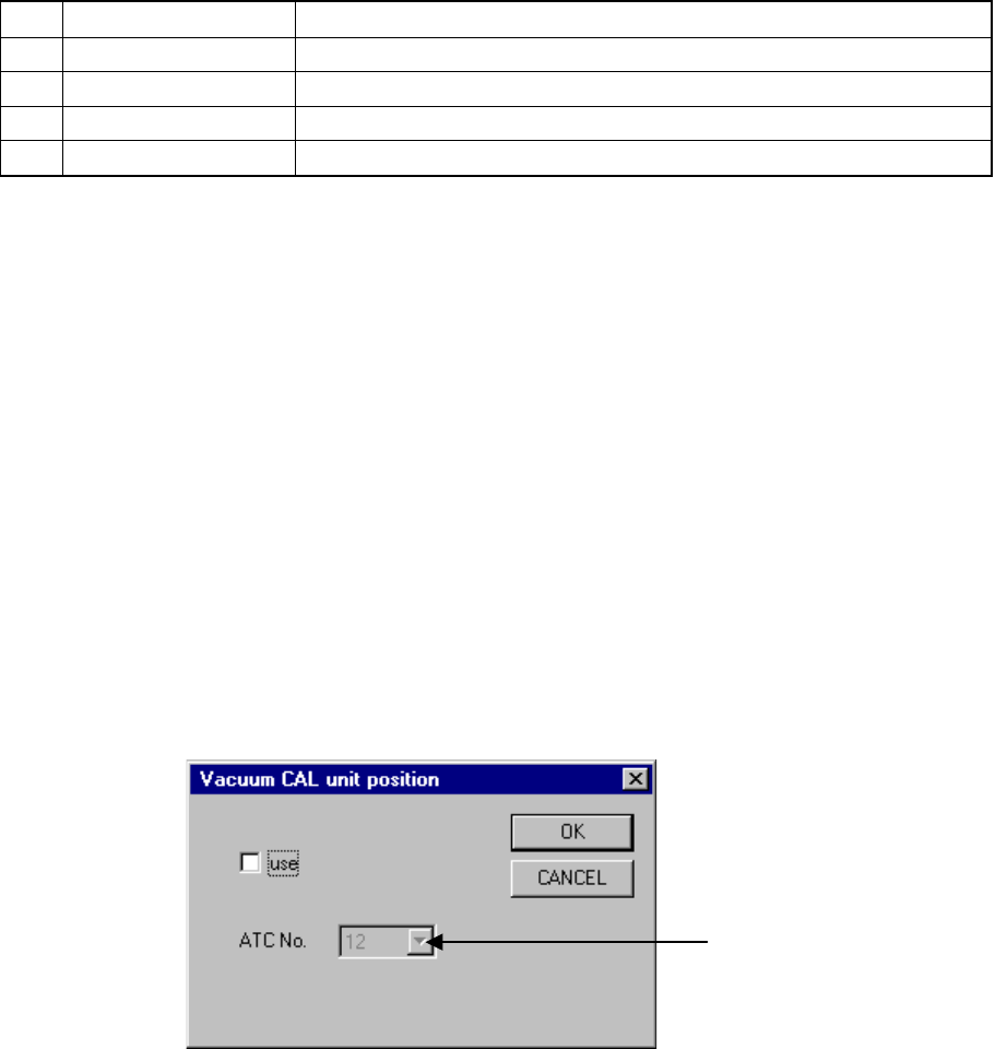
⑤ Vacuum calibration unit position (VacUnit)
− Set the vacuum calibration post position attached on the ATC.
− When you click the button for setting the vacuum calibration position,
the “Vacuum CAL unit position” dialog box appears on the screen as
shown in Figure 7.2.2.1.1 (1).
− The number displayed left to the button indicates the ATC number
currently set. If any number is not set, “***” is displayed.
Figure 7.2.2.1.1 (1) “Vacuum CAL unit position” dialog box
ATC number selection list box