KE2010.Instruction Manual.Ver.2.01,Rev.08.pdf - 第552页
7 − 15 − Check or uncheck the check box “use” t o specif y w hether to use the vacuum calibration unit or not . This check box is not checked as default . − If t his check box is not check ed, you cannot select any A TC …
7 − 14
② Noz. kind
− Set the type of a nozzle to be mounted.
− This item is set automatically with the machine only.
However, you have to set the setting item “VacUnit” on the “Vacuum
CAL unit position” dialog box as shown at ⑤ below.
− Available nozzle types are shown in the table below:
Table 7.2.2.1.2 Available nozzle types
No. Setting item Description
1 normal Normal nozzle
2 T-type Cleaner type nozzle
3 Gripper Gripper nozzle
4 VacUnit Vacuum calibration unit
③ Setting the vacuum value: Vacuum
− Set the vacuum value when a nozzle is mounted.
− Only automatic setting is available.
④ Setting the nozzle height: Noz. height
− Set the offset value of the mounted nozzle with respect to the reference
nozzle.
− Only automatic setting is available.
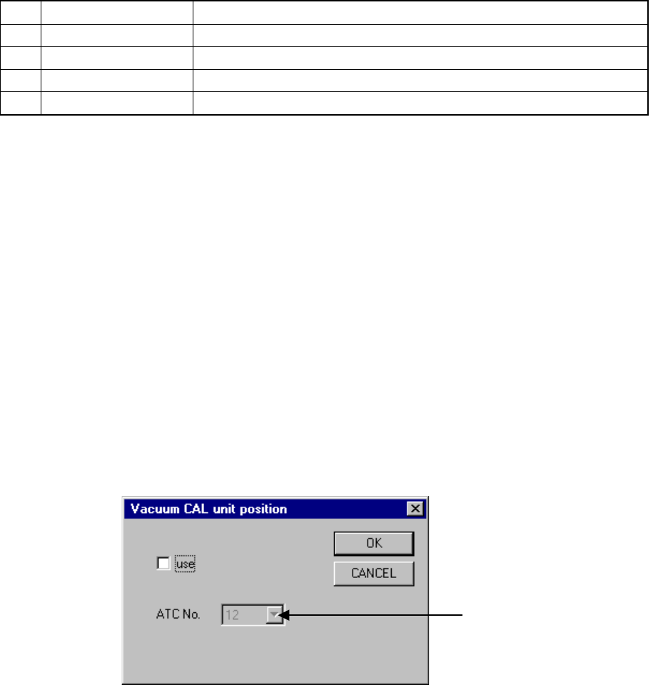
⑤ Vacuum calibration unit position (VacUnit)
− Set the vacuum calibration post position attached on the ATC.
− When you click the button for setting the vacuum calibration position,
the “Vacuum CAL unit position” dialog box appears on the screen as
shown in Figure 7.2.2.1.1 (1).
− The number displayed left to the button indicates the ATC number
currently set. If any number is not set, “***” is displayed.
Figure 7.2.2.1.1 (1) “Vacuum CAL unit position” dialog box
ATC number selection list box
7 − 15
− Check or uncheck the check box “use” to specify whether to use the
vacuum calibration unit or not. This check box is not checked as
default.
− If this check box is not checked, you cannot select any ATC number.
− If this check box is checked, select the ATC number on which the
vacuum calibration unit is attached from the ATC number selection list
box.
When this dialog box appears for the first time, the default number
unique to the model appears as the ATC number. If the vacuum
calibration unit cannot be attached at this default position, the machine
displays the smallest ATC number on which the unit can be attached.
− You cannot select the ATC numbers shown below:
The table below indicates the ATC positions on which you cannot attach a
vacuum calibration unit physically. These unavailable positions vary
depending on the model you use.
The ATC number selection list box does not display these positions.
Table 7.2.2.1.3 ATC numbers you cannot select
No. Model Unavailable positions
1 2010 4, 5, 11, 12, 16, 17, 23, 24
2 2020 1, 2, 10, 11, 16, 17 , 25, 26, A, B,
3 2030
L1 ~ L21, R5 ~ R21
4 2040 4, 5, 11, 12, B
5 2020S 1, 7, 8, 11, 17, 18, 21, 27, 28, B
− You can select ATC numbers that are not validated although you
assigned a nozzle to them already. In the same manner, you cannot
select an ATC number whose nozzle assignment is canceled unless the
cancel operation is validated.
− Even though you change the vacuum calibration unit position on the
dialog box above, it cannot be effective unless you click the <OK> or
<Apply> button on the dialog box above.
− If nozzles are assigned to all ATC positions or if there is no ATC position
to which a vacuum calibration unit can be assigned, the button for
setting the position is dimmed and you cannot specify a vacuum
calibration unit.
In such as case, cancel nozzle assignment of an available ATC position.
To do so, erase the nozzle number already assigned to an ATC position
on the “ATC nozzle setup” dialog box, and cancel the nozzle assignment.
Then click the <APPLY> button to validate your cancel operation.
− You cannot assign a vacuum calibration unit to an ATC position to which
a nozzle is already assigned and validated or an ATC position where a
vacuum calibration unit cannot be attached physically (this varies
depending on the model you use). (Note that these ATC positions are
not displayed on the list box.)
7 − 16
− When you check the check box “use” and validate your setting, the ATC
number you set is dimmed on the “ATC nozzle setup” dialog box and
you cannot check it. (“VacUnit” is displayed as the nozzle type.)
− To disable the vacuum calibration unit position, uncheck the check box
“use”. You can assign a nozzle to an ATC position to which you already
assigned a vacuum calibration unit on the “ATC nozzle setup” dialog
box.
• Automatic setting
− When the F3 key is pressed, the machine puts the nozzle on a head
whose ATC number is focused and sets the necessary values.
− When the Auto button is selected and the ENTER key is pressed, the
Automatic ATC number selection dialog box shown in Figure 7.2.2.1.2
appears. By selecting OK button and pressing the ENTER key,
nozzles is automatically in order of the marked ATC numbers.
1) The height of the tip of the nozzle mounted is measured to obtain the
nozzle height.
2) The nozzle number is set according to the size of the nozzle mounted.
3) The vacuum value is obtained and set with the nozzle being mounted.