KE2010.Instruction Manual.Ver.2.01,Rev.08.pdf - 第555页
7 − 18 Figure 7.2.2. 1.2 “Registered nozzl e no. table” dial og box Figure 7.2.2. 1.3 Nozzle informatio n not-registered error dialog box CA UTION W hen you click the F3 key, the head moves to allow you to attach/detach …

7 − 17
Notes: 1)
When there are two or more ATCs to be set automatically, automatic
setting can be terminated by pressing the STOP switch.
When the STOP switch is pressed during automatic setting, the machine
asks you whether to terminate the operation. Selecting <Yes>
terminates the operation immediately. Selecting <No> continues the
operation.
Even though you click the Cancel button, you cannot terminate the
automatic setting operation.
2)
When carrying out the automatic setting, the nozzle number is also set
automatically, so, you do not have to enter it.
If the nozzle number entered before automatic setting is different from
the one obtained by the automatic setting, the nozzle number
automatically set is preferred.
3)
Since the nozzle type is automatically set when you perform the
automatic setting operation, you do not have to enter it.
4)
When the size of a nozzle obtained automatically is different from that of
the standard nozzle, the number of a customized nozzle is set
automatically if the obtained size matches the size registered in the
customized nozzle information.
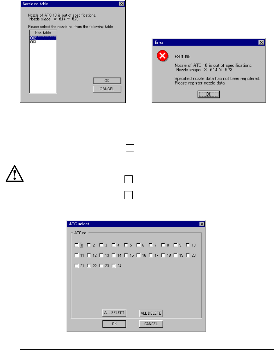
If the obtained size matches two or more sizes registered in the
customized nozzle information, the system displays the “Registered
nozzle no. table” dialog box as shown in Figure 7.2.2.1.2. Select the
appropriate one from this table. The selected nozzle number is set to
the corresponding ATC.
Even though you click the <CANCEL> button at this point, the nozzle
numbers already set will not change. If you have not set a nozzle to
any ATC position, no nozzle number is set here. Manually enter the
nozzle number.
5)
If the obtained size does not match any one registered in the customized
nozzle information, or if no nozzle information is registered, the system
displays the nozzle information not-registered error dialog box as shown
in Figure 7.2.2.1.3. Register the appropriate nozzle information from a
floppy disk.
7 − 18
Figure 7.2.2.1.2
“Registered nozzle no. table” dialog box
Figure 7.2.2.1.3
Nozzle information not-registered error
dialog box
CAUTION
When you click the F3 key, the head moves to allow you to
attach/detach a nozzle.
To avoid a risk of injury, do not place your hand in the machine, nor
move your face or head close to the machine.
Before clicking the F3 key, check to see if there is no one who is
working in the machine.
Before clicking the F3 key, check to see if there is no obstacle (tool or
jig) left or attached in the machine.
Figure 7.2.2.1.4 ATC select dialog box (Screen example when a KE-2020 is used)
Note : The displayed available ATC numbers vary depending on the model you use
(3) Purpose
The nozzle height offset is used to finely control the nozzle height for laser
measurement of the components. This value, used in combination with the
non-nozzle vacuum value, determines whether the nozzle or component in
question is available or not. Note that this setting value is a supplementary
information for the nozzle and component detection because it can be detected
using the laser.
7 − 19
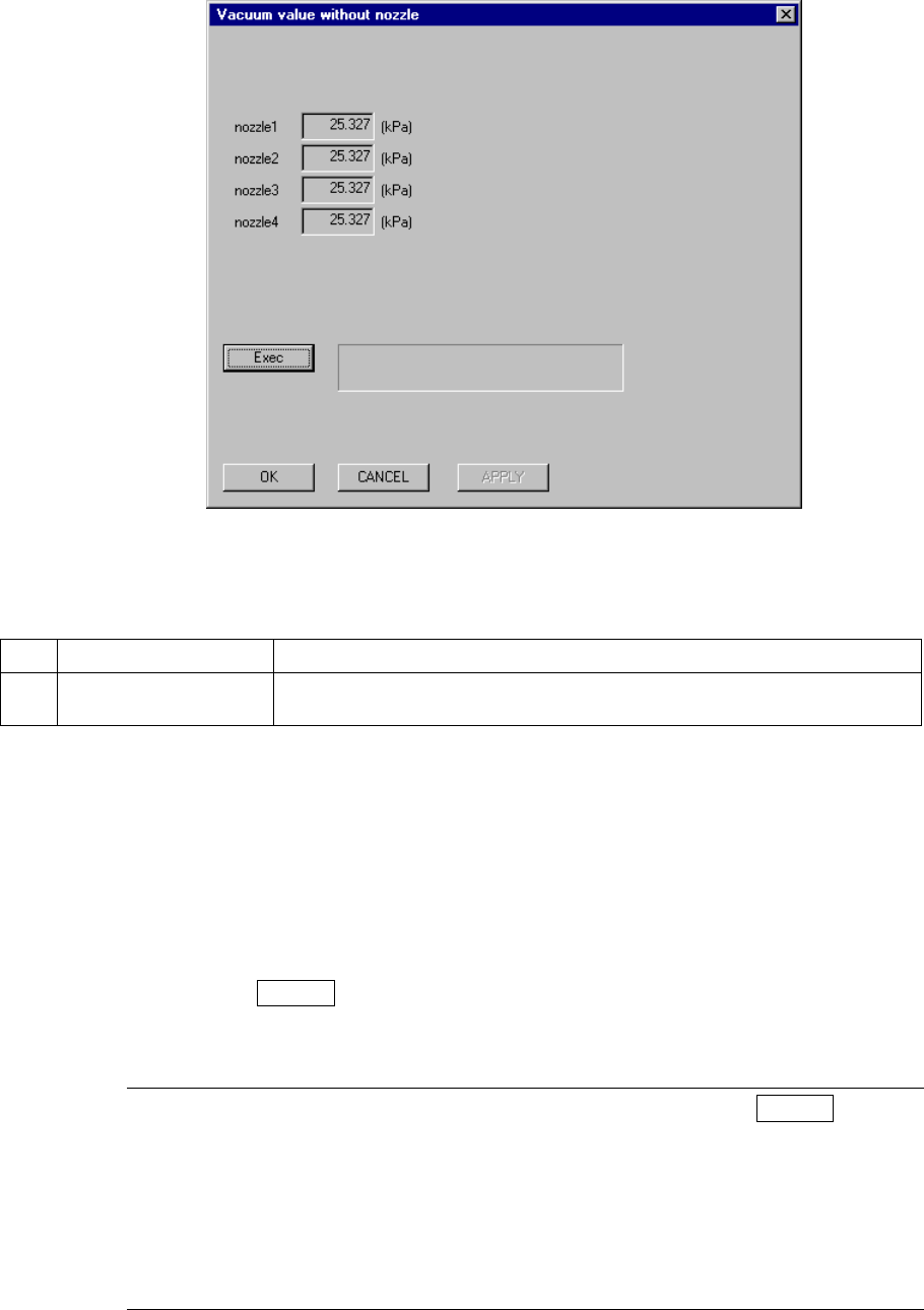
7.2.2.2 Vacuum value without nozzle
A screen appears as shown in Figure 7.2.2.2.1 “Vacuum value without nozzle dialog
box” when [Vacuum value without nozzle] is selected from the [Setting Group]
menu.
Figure 7.2.2.2.1 Vacuum value without nozzle setting dialog box
(1) Setting items
No. Item Description
1 Vacuum value without
nozzle
The vacuum value without the nozzle attached (for automatic operation only)
(2) How to set
−
By the Head button
Using the field selection key, select the desired Head, and click the <DONE>
button to obtain the vacuum value. When a nozzle is mounted to the head,
the nozzle is returned first and then the vacuum value is obtained.
−
By Teaching
Using the device key of the HOD, enter Teaching mode. Check that the
head whose vacuum value to be obtained is set as the device and then
press the ENTER key of the HOD.
When the desired head is set as the device when teaching mode, the
vacuum of the head is turned ON.
Notes: 1) Before exiting from Teaching mode by pressing the ENTER key of
the HOD, be sure to check that the vacuum of the head is turned
ON.
2) When entered Teaching mode by selecting a device other than a
head, the vacuum is not turned ON automatically. In this case,
press the VAC key of the HOD to turn ON the vacuum.
Standard value is –300 to –120 (mmHg).