KE2010.Instruction Manual.Ver.2.01,Rev.08.pdf - 第56页
1 − 39 ⑥ is a 9-Pin connect or f or the t rackball. See Table 1.4. 5 for the pin assignm ent of this tr ackball connect or. ⑦ is a 50-Pin connect or f or the k eyboard. See Table 1.4. 4 for the pin assignm ent of this k …
1 − 38
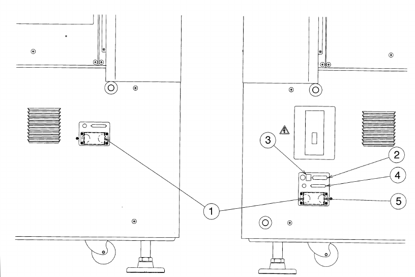
1.4 Interface With Extenal Devices
(1) ①
is the 14-Pin READY OUT (IN) connector for use when the machine is
configured with other equipment in an on-line environment.
The pin layout (assignment) of the connector for a Ready OUT (IN) signal differs
as shown in Tables 1.4.1 and 1.4.2 depending on the board transfer direction
(from left to right, and from right to left, respectively).
See Table 1.4.3 for the pin assignment of this printer connector.
(2) ②
is a DSub 25-Pin connector for the printer (conforming to the Centronics
Interface standards).
③
is an Ethernet connector (8-pin modular type connector).
See Table 1.4.6 for the pin assignment of this Ethernet connector.
Figure 1.4.1 Left side panel of the main unit Figure 1.4.2 Right side panel of the main
unit
④
is a connector for interface with a matrix tray changer (50-pin).
⑤
is a power connector for a matrix tray changer (7-pin).
1 − 39
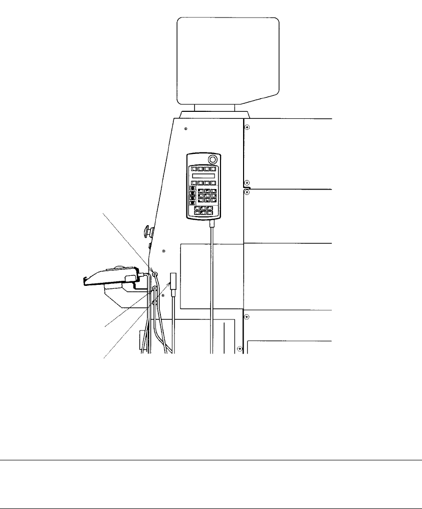
⑥
is a 9-Pin connector for the trackball.
See Table 1.4.5 for the pin assignment of this trackball connector.
⑦
is a 50-Pin connector for the keyboard.
See Table 1.4.4 for the pin assignment of this keyboard connector.
⑧
is a 5-Pin connector for the Hand-held operating device (HOD).
Figure 1.4.3 Machine right side panel
Note: The shape of the track ball connector and that of the keyboard connector is
the same. If you accidentally make the wrong connections, the system will
not be started up.
⑥
⑧
⑦
1 − 40
Table 1.4.1 List of connectors on the left side panel
Signal name (left to right) Signal name (right to left) Connector used
1 READY OUT READY IN
2 READY OUT READY IN GND
3 BOAD AVAILABLE IN BOAD AVAILABLE OUT
4 BOAD AVAILABLE IN GND BOAD AVAILABLE OUT
5 N.C. N.C.
6 N.C. N.C.
7 N.C. N.C.
8 N.C. N.C.
9 N.C. N.C.
10 N.C. N.C.
11 N.C. N.C.
12 N.C. N.C.
13 N.C. N.C.
14 N.C. N.C.
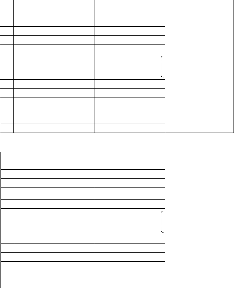
Table 1.4.2 List of connectors on the right side panel
Signal name (left to right) Signal name (right to left) Connector used
1
READY IN READY OUT
2
READY IN GND READY OUT
3
BOAD AVAILABLE OUT BOAD AVAILABLE IN
4
BOAD AVAILABLE OUT BOAD AVAILABLE IN
GND
5
N.C. N.C.
6
N.C. N.C.
7
N.C. N.C.
8
N.C. N.C.
9
N.C. N.C.
10
N.C. N.C.
11
N.C. N.C.
12
N.C. N.C.
13
N.C. N.C.
14
N.C. N.C.
(Connection of the
cable end 206044-1)
AMP
206043-1
(Connection of the
cable end 206044-1)
AMP
206043-1