KE2010.Instruction Manual.Ver.2.01,Rev.08.pdf - 第564页
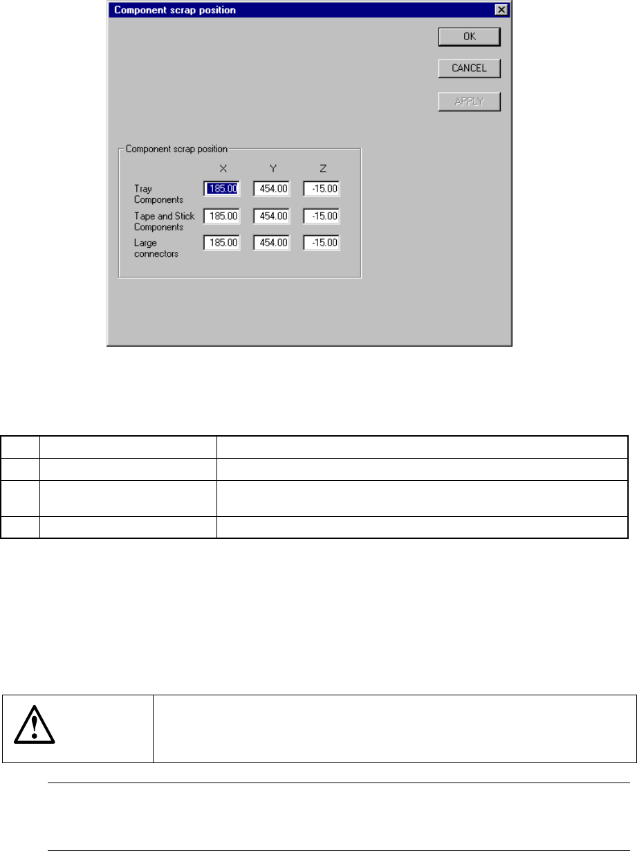
7 − 27 7.2.2.7 Component scrap position A screen appears as shown in Figure 7.2. 2.7.1 “ Component scrap position set ting dialog box” when [Component scrap posit ion] is selected f rom t he [Setting Group] menu. Figure …
7 − 26
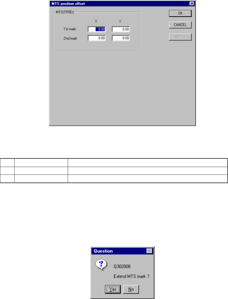
7.2.2.6 MTS position offset
When you select the [MTS position offset] command, the "MTS position offset setting"
dialog box appears on the screen as shown in Figure 7.2.2.6.1.
Figure 7.2.2.6.1 MTS position offset setting dialog box
(1) Setting items
No. Item Description
1 1'st mark (X,Y) First mark position of the MTS
2 2'nd mark (X, Y) Second mark position of the MTS
(2) Setting the position
− Key in X and Y coordinate values directly from the keyboard.
− Use the HOD to teach and enter the coordinates. In this case, if either X or
Y is in focus, both values are taught, then entered.
− When you select the device key of the HOD, the following message appears
on the screen. When you click the <Yes> button, the MTS bank mark is
found out.
Figure 7.2.2.6.2 Question dialog box
7 − 27
7.2.2.7 Component scrap position
A screen appears as shown in Figure 7.2.2.7.1 “Component scrap position setting
dialog box” when [Component scrap position] is selected from the [Setting Group]
menu.
Figure 7.2.2.7.1 Component scrap position setting dialog box
(1) Setting items
No. Item Description
1 Tray Components (X, Y, Z) The scrap position for IC components
2 Tape & Stick Components
(X, Y, Z)
The scrap position for chip components
3 Large Connectors (X, Y, Z) The scrap position for large components
(2) Setting the position
− Key in X, Y, and Z coordinate values directly from the keyboard.
− Use the HOD to teach and enter the coordinates. In this case, if either X or
Y is in focus, both values are taught, then entered.
− Z must be in focus to teach the Z coordinate.
CAUTION
To avoid a risk of injury, do not place your hand in the machine, nor
move your face or head close to the machine during operation of the
HOD.
Note: The left head cannot be as the component scrap position on the right side.
The right head cannot be set to the component scrap position on the left side
either.
7 − 28
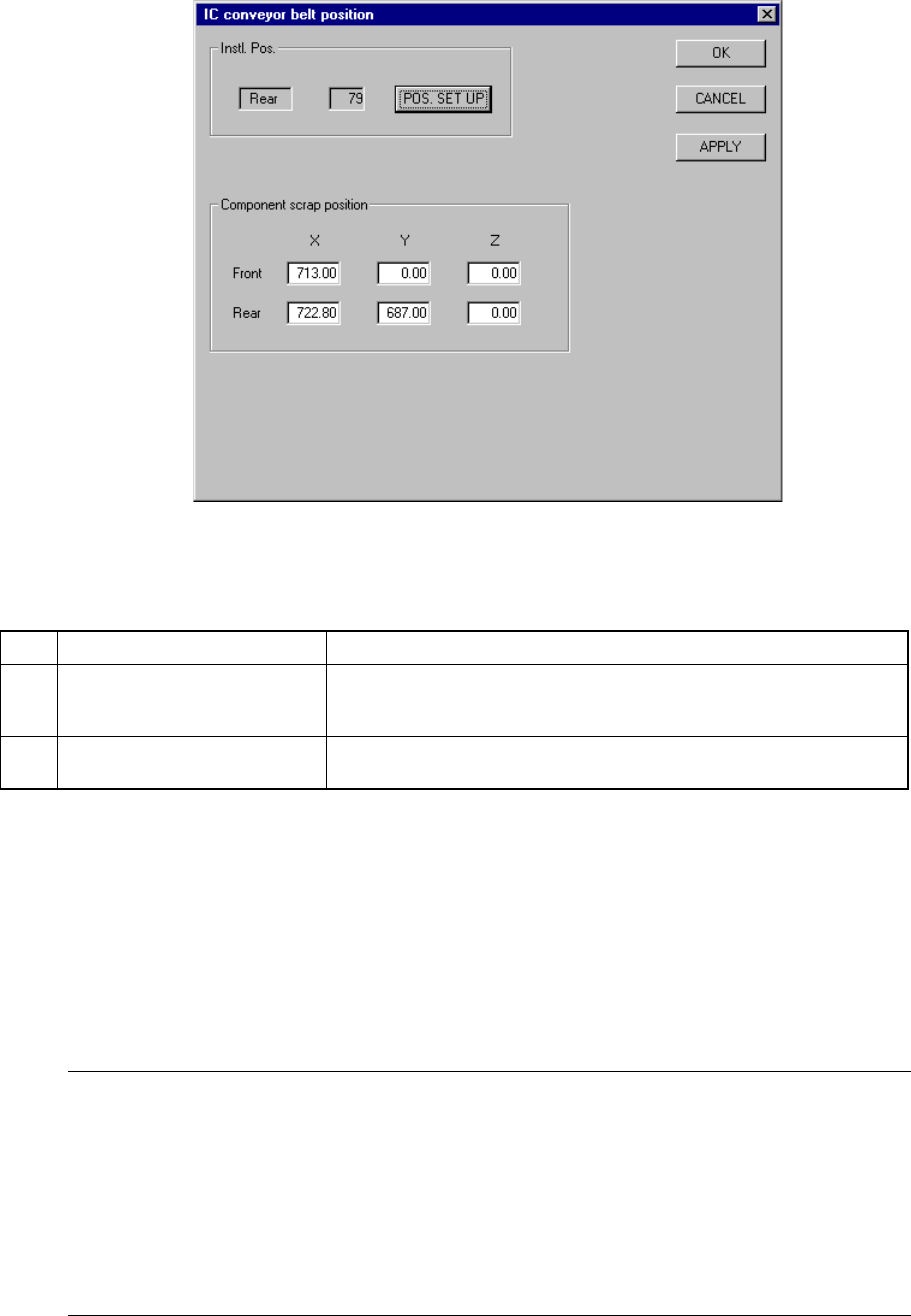
7.2.2.8 IC conveyor belt position
When you select the [IC collection belt position] command, the "IC collection belt
position setting" dialog box appears on the screen as shown in Figure 7.2.2.8.1.
Figure 7.2.2.8.1 IC collection belt position setting dialog box
(1) Setting items
No. Item Description
1 Instl. Pos (Installation position)
(Front/Rear, Feeder mounting
hole number)
IC collection belt installation position
2 Component scrap position
(X, Y and Z)
Component scrap position on the IC collection belt
(2) Setting the position
① How to install the IC collection belt
− Set the IC collection belt installation position.
− When you click the <POS.SET UP> button, the "Instl. Pos." dialog box
appears on the screen as shown in Figure 7.2.2.8.2.
− Use the "Front" or "Rear" radio button to set the side.
− Enter the feeder mounting hole number in the "Feeder No." edit box.
Notes:
- The range of feeder mounting hole number should be within the area the right
head can move over.
- When you click the <OK> button to quit the dialog box shown in Figure 7.2.2.8.2,
the system automatically calculates the component scrap position. Perform
teaching to check this calculated scrap position.
- If you optimize a production program before you set the IC collection belt position,
the feeder and the IC collection belt may overlap one another.