KE2010.Instruction Manual.Ver.2.01,Rev.08.pdf - 第574页
7 − 37 7.2.2.10. 4 MTC/MTS Device enable W hen y ou select t he "MTC/MTS Device enable" tab, the "MTC/MTS Device enable setting" dialog box appears on the screen. Figure 7.2.2. 10.4 MTC/M TS Device en…

7 − 36
(3) Production operation
Table 7.2.2.10.3 Placement when set to “Unused”
No. Unit Production operation
1 Stops by detected
feeder float
The XY speed becomes slower when the sensor detects feeder floating while
the XY axe are moving.
When the sensor detects feeder floating before the XY axes moves, the
machine asks the operator whether to retry the sensor detection operation.
When the operator selects “Retry”, the sensor reconfirms feeder floating.
When he or she selects “Cancel”, the production is terminated.
2 Bank mark Recognition
(front, rear)
The function is disabled but placement of components is carried out.
3 SOT Inspect Stage You cannot specify the SOT direction check on the tracking menu.
4 Back Master-Bank
[Non-stop]
Places the master bank on the front (“Front” means the front side of the main
unit.).
Table 7.2.2.10.4 Placement operation to be performed if you check any of the
check boxes of the “Optimization function” group
No. Unit Production operation
1 Disable feeder
optimization
The “Pick Data” option displayed on the dialog box that appears when you
execute the [Optimization] command on the “Optimization” menu of the
Program Editor utility is fixed to “Auto assign all data”. You cannot select
any other option.
2 Disable nozzle
optimization
The “Nozzle” option displayed on the dialog box that appears when you
execute the [Optimization] command on the “Optimization” menu of the
Program Editing utility is fixed to “Use permanent nozzle setup from MSL
Setup”. You cannot select any other option.
7 − 37
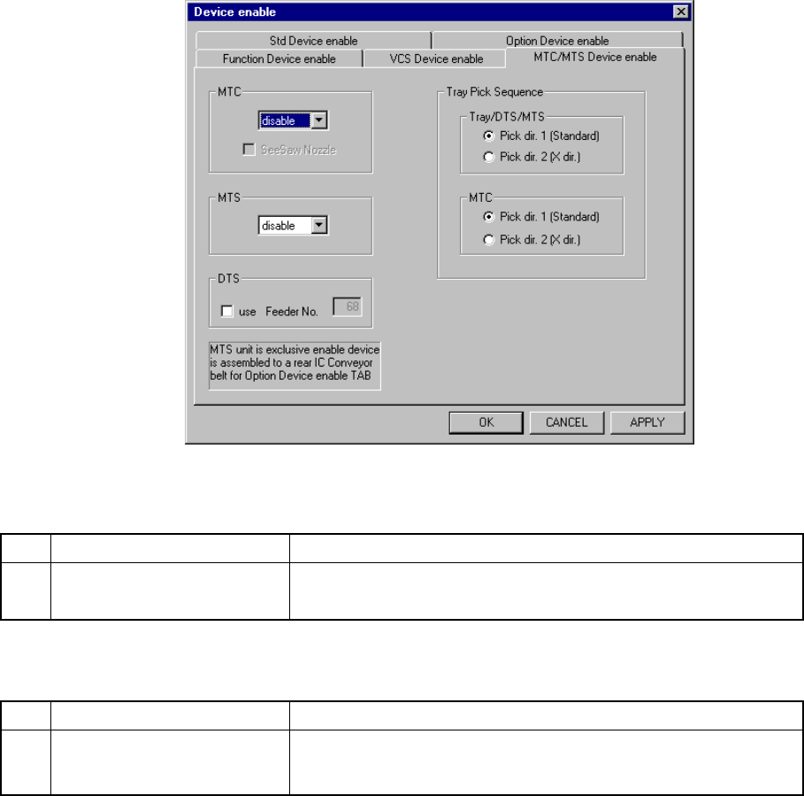
7.2.2.10.4 MTC/MTS Device enable
When you select the "MTC/MTS Device enable" tab, the "MTC/MTS Device enable
setting" dialog box appears on the screen.
Figure 7.2.2.10.4 MTC/MTS Device enable setting dialog box
(1) Setting items
No. Item Description
1 MTC/MTS
Enables or disables an MTC/MTS unit.
Set the type of MTS, MTS or DTS to be used here.
If the production program requires the unit above to complete component
placement, Table 7.2.2.10.4 shows whether production is to be performed
actually or not.
No. Item Description
2 Tray Pick Sequence Sets the order tray components are picked up:
sets the direction on which components are to be picked up per
available unit.
If the production program requires the unit above to complete component
placement, see Table 7.2.2.10.6 to check the production operation the system
actually performs.
(2) Setting the position
- Specify the device to be used with the combo box.
- Only when an MTC is equipped with a seesaw nozzle, check the check box
“Seesaw nozzle”
- For a DTS, check the check box "use", then enter the feeder mounting hole
number to the "Feeder No." edit box.
- You cannot connect both the MTC and MTS to the machine at the same
time.
- You cannot connect both the MTS and DTS to the machine at the same
time.

7 − 38
- If you check the rear IC Conveyor belt on the "Option Device enable setting"
dialog box, you cannot set the MTS.
- Specify the menu item “Tray Pick Sequence” according to the following two
groups of units:
①Tray, DTs and MTS
②MTC
- Two types of orders in which tray components are to be picked are available:
click the corresponding radio button:
①Pick dir. 1 (Standard)
②Pick dir. 2 (X dir.)
Default: Pick dir. 1 (Standard)
- You can select either button regardless of the “disable”/”enable” setting of
the menu item “MTC”, “MTS”, or “DTS”.
- Even though the menu item “MTC” or the corresponding unit is set to
“disable”, you can set this menu item.
(3) Production operation
Table 7.2.2.10.5 Placement when set to "Unused"
No. Unit Production operation
1 MTC Components which are fed from the MTC are to be skipped.
2 MTS Components which are fed from the MTS are to be skipped.
3 DTS Components which are fed from the DTS are to be skipped.
Table 7.2.2.10.6 Placement when “Pick dir. 2 (X dir.)” is selected
No. Unit Production operation
1 Tray Starts picking up components from the start position (rear and far side)
toward the right direction when viewed from the front.
2 DTS Starts picking up components from the start position (rear and far side)
toward the right direction when viewed from the front.
3 MTS Starts picking up components from the start position (rear and far side)
toward the right direction when viewed from the front.
Pick-up order
MTC Starts picking up components from the start position (rear and far side)
toward the right direction when viewed from the front.