KE2010.Instruction Manual.Ver.2.01,Rev.08.pdf - 第580页
7 − 43 7.2.2.13 Vacuum t able W hen y ou select [V acuum table] f rom the [Sett ing Gr oup] menu, t he “V acuum t able” dialog box appears as shown in Figure 7.2. 2.13.1. Figure 7.2.2. 13.1 “V acuum table” dialog box (1)…
7 − 42
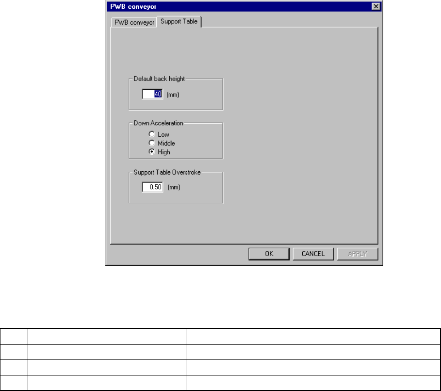
7.2.2.12.2 Support Table
When you click the “Support Table” tab, the “Support Table” setting dialog box
appears as shown in Figure 7.2.2.12.2.
Figure 7.2.2.12.2 “Support Table” setting dialog box
(1) Setting items
No. Item Description
1 Default back height Sets the PWB position lower limit on the support table.
2 Down Acceleration Sets the acceleration of the support table.
3 Support Table Overstroke Sets how much the support table should be pushed in.
(2) How to set
① Default back height
− Specify the value in the range from 5 to 40.
The unit is fixed to mm.
② Down Acceleration
− With using the radio button, set one of three steps; Low, Middle, and
High (default: High).
③ Support Table Overstroke
− Specify the value in the range from 0.00 to 5.00.
7 − 43
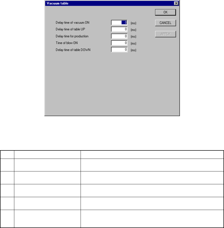
7.2.2.13 Vacuum table
When you select [Vacuum table] from the [Setting Group] menu, the “Vacuum table”
dialog box appears as shown in Figure 7.2.2.13.1.
Figure 7.2.2.13.1 “Vacuum table” dialog box
(1) Setting items
No. Item Description
1 Delay time of vacuum ON Sets the time of period since the STOP sensor is activated until
vacuum is turned on when a board is clamped.
2 Delay time of table UP Sets the time of period since vacuum is turned on until the support
plate starts moving up when a board is clamped.
3 Delay time for production Sets the time of period required to detect the ON status of the vacuum
sensor when a board is clamped.
4 Time of blow ON Sets the time of period while the blow function is set to ON when the
clamped board is released.
5 Delay time of table DOWN Sets the time of period since the system detects the vacuum sensor
OFF status until the support plate starts moving down when the
clamped board is released.
(2) How to set
− Enter a value directly form a keyboard.
− The input range is from 0 to 1000.
− The unit is fixed to “ms”.
− The defaults of all the items are “0 ms”.
− When the “Vacuum table” is set to “disable” on the “Option Device enable”
tab, these menu items are dimmed.
7 − 44
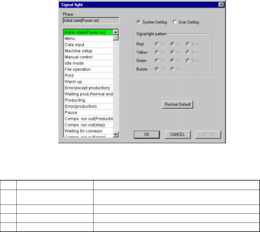
7.2.2.14 Signal light
A screen as shown in Figure 7.2.2.14.1 “Signal light setting dialog box” appears
when [Signal light] is selected on the [Setting Group] menu.
Figure 7.2.2.14.1 Signal light setting dialog box
(1) Setting items
No. Item Description
1 Signal light pattern
(Red, Yellow, Green)
Sets the light pattern of the signal light in each operation phase.
2 Signal light pattern (Buzzer) Sets ON/OFF of the buzzer in each operation phase.
3 System setting/User setting Sets the data used for a user signal pattern.
4 System Default Copies the system setting data to the user setting data.
(2) How to set
① Signal light (Red, Yellow, Green)
− Using the radio button, set on, off, or blink.
② Buzzer
− Using the radio button, set off or on.
③ System Setting/User Setting
− Select the data to be used with either of these radio buttons.
− Selection of the “System Setting” radio button allows you to see the
settings of the system initial values only. You cannot change them.