KE2010.Instruction Manual.Ver.2.01,Rev.08.pdf - 第591页
8 − 2 (1) Im mediately af ter star ting The “ Manual control” initial screen shown below appears when selecting the [Manual Operation] comm and on the [Set up] menu invoked f rom the menu bar . Figure 8.1.1 Manual contro…
8 − 1
CHAPTER 8 MANUAL CONTROL
8.1 Overview
The following table shows the manual control items.
Table 8.1.1 Manual control items
Main menu Sub menu Description
1 Head control XY axes movement control and display in X and Y
coordinates relative to each head.
Z and θ axes movement control and coordinate display of
each head Vacuum control, blow control, and pressure
value display of each head.
2 Head device
control
XY axes movement control and display in X and Y
coordinates of each head device (OCC, bad mark sensor,
HMS).
Control of each head device and display of sensor status
1 Head
3 Laser control Vacuum control of each head, and vacuum ON/OFF display
Z axis movement control and coordinate display of each
head algorithm change
Measurement and result display
Image display
Edge check and Edge check display
1 Independent
control of
conveyor
Stopper control, edge reference cylinder control, support
table control, ready out control, board available out control,
transport motor control, each sensor of transport system,
signal status display, support table stopper sensor control,
and Entrance (IN)/Exit (OUT) shutter control
2 Automatic control
of conveyor
Automatic transport control, each sensor of transport
system, signal status display, and movement control
between the PWB stations
3 Auto width
conveyor control
Automatic PWB width alignment operation control, display
of the PWB transport width
Status display of each conveyor sensor
4 Movable station
control *1
Control of the cylinder which checks if there is a PWB,
display of the cylinder and sensor status, control of the Y
axis movable station and display of coordinates
2 Conveyor
5 Vacuum Table Control of vacuum of the vacuum table, control of the blow
function, and control of the support table.
3 Vision 1 VCS control *2 Control of the light and state display
Control of the side light board up/down cylinder and state
display
1 MTC control Shuttle control, tray control, pick control, and status display
Control of the PWB transport width adjustment operation
and display of the PWB transport width
2 Knock pin control Control of the feeder knock pin and control of the feeder
position indicator
3 DTS control Tray control and state display
4 Feeder
4 MTS control Tray control and state display
1 ATC control ATC slide plate control, sensor status display, and nozzle
suction control
2 Signal light control Signal light control, buzzer control, and status display
3 Component
verification
Probe control, component measurement, and status display
4 SOT inspect unit Vacuum control and state display
5 Calibration block
control
LED control, vacuum control and state display
6 Other sensors Status display of IC component discarding conveyor stop
sensor, etc.
5 Others
7 Driver state Status display of the X, Y, Z, and theta axes drivers
*1 Supported by a KE-2030.
*2 Supported by a KE-2020 and KE-2040.
8 − 2
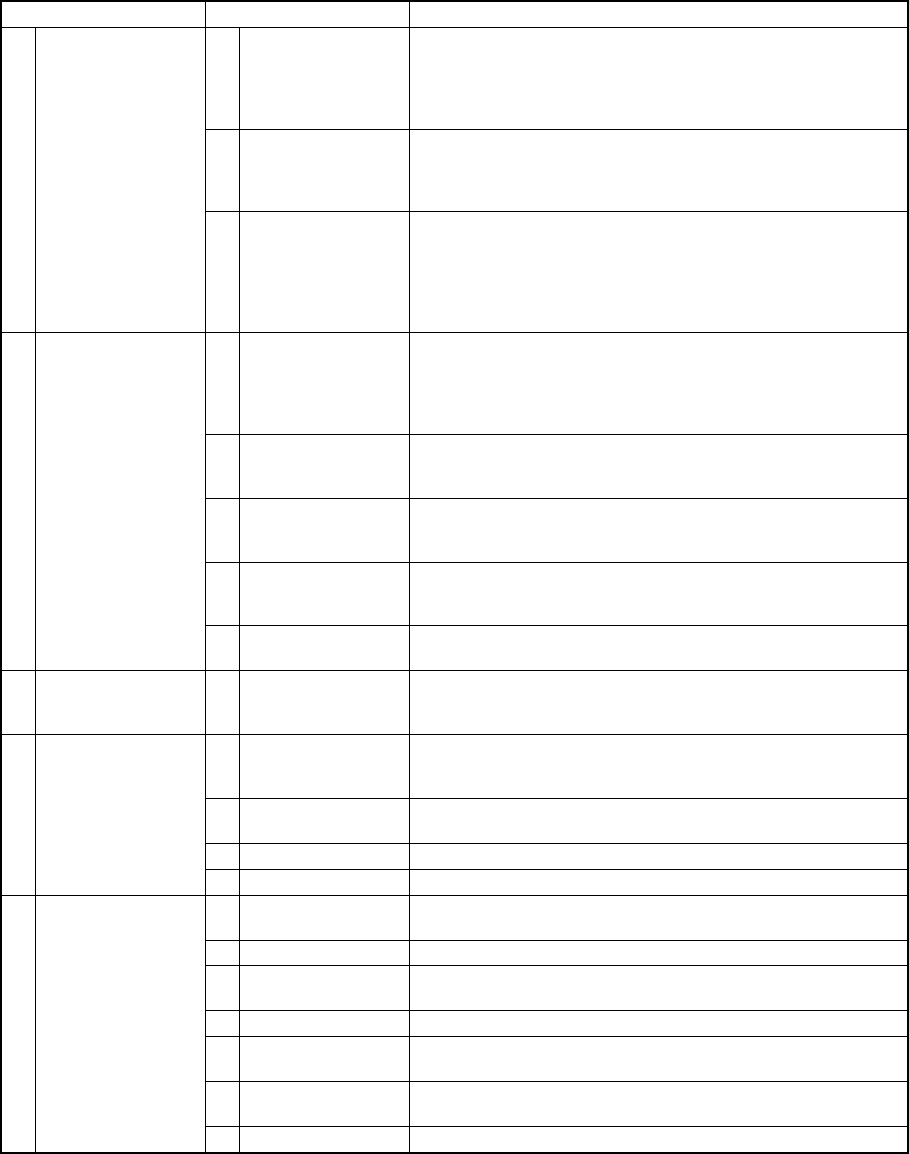
(1) Immediately after starting
The “Manual control” initial screen shown below appears when selecting the
[Manual Operation] command on the [Setup] menu invoked from the menu bar.
Figure 8.1.1 Manual control initial screen
(2) Commands
No summary of a command appears on the message line while you are selecting
a command on the "Manual control" menu.
1) File
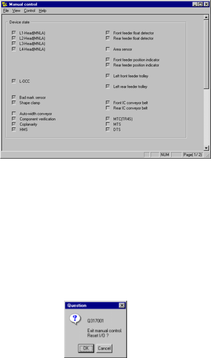
When you select the [Exiting Application] command, the dialog box shown in
Figure 8.1.2a, which asks you whether to set each I/O device safety
direction, appears on the screen.
When you click the <OK> button on this dialog box, the system sets the
each I/O device safety direction, then quits this application.
When you click the <Cancel> button, the system cancels the [Exiting
Application] command.
Figure 8.1.2a "Question - to reset I/O" dialog box
8 − 3
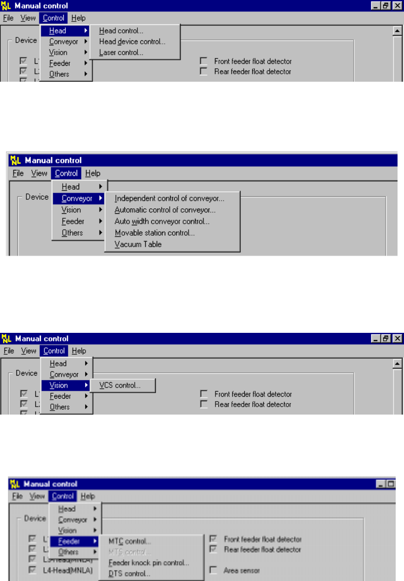
2) Ctrl
− Head
Figure 8.1.2 Head pull-down menu
− Conveyor
Figure 8.1.3 Conveyor pull-down menu
− Vision
Figure 8.1.4 Vision pull-down menu
− Feeder
Figure 8.1.5 Feeder pull-down menu