KE2010.Instruction Manual.Ver.2.01,Rev.08.pdf - 第596页
8 − 7 Figure 8.1.7. 1 List of the units that can be controlled by each model W hen you enter the coordinates t o which you w ant the head to m ove, then select the <EXEC> butt on or press the F3 k ey , the head m o…
8 − 6
1) XY move
Moves the selected head to the selected position along the XY, axes based on
the selection unit reference position.
You cannot select a menu item to which the selected head cannot move by
referring to the selected unit position.
You can move the head to the standard position by referring to the selected
control unit position or to the desired coordinates.
As the standard position, you can move the head to: the origin, CAL block first
mark position, waiting position (default, when a nozzle is removed, or
user-designated), reference pin position, follower pin position, MTC shuttle
pick-up position, component discarding position (IC, chip, large component),
VCS position, CVS position, bank mark position, vacuum calibration position and
so on.
When you select the position to which you want to move the head on the pop-up
menu, the head moves there by referring to the selected control unit position.
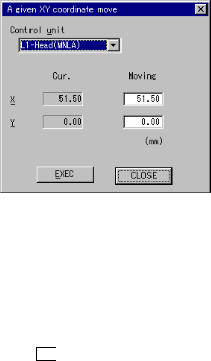
When you select to move the head to the desired coordinates, the “A given XY
coordinate move” dialog box appears on the screen as shown in Figure 8.1.7.
Figure 8.1.7 “A given XY coordinate move” dialog box
Select the unit to be controlled in the combo box.
You cannot select any unit which is not checked (not installed) at the “Option”
setting of the MS parameters.
This setting does not affect the setting of the “Device enable” menu invoked from
the Machine Setup menu (you can select a not-checked (not used) unit).
When you press the ALT key while holding the down arrow key, one of the
following list appears on the screen depending on the model you use.
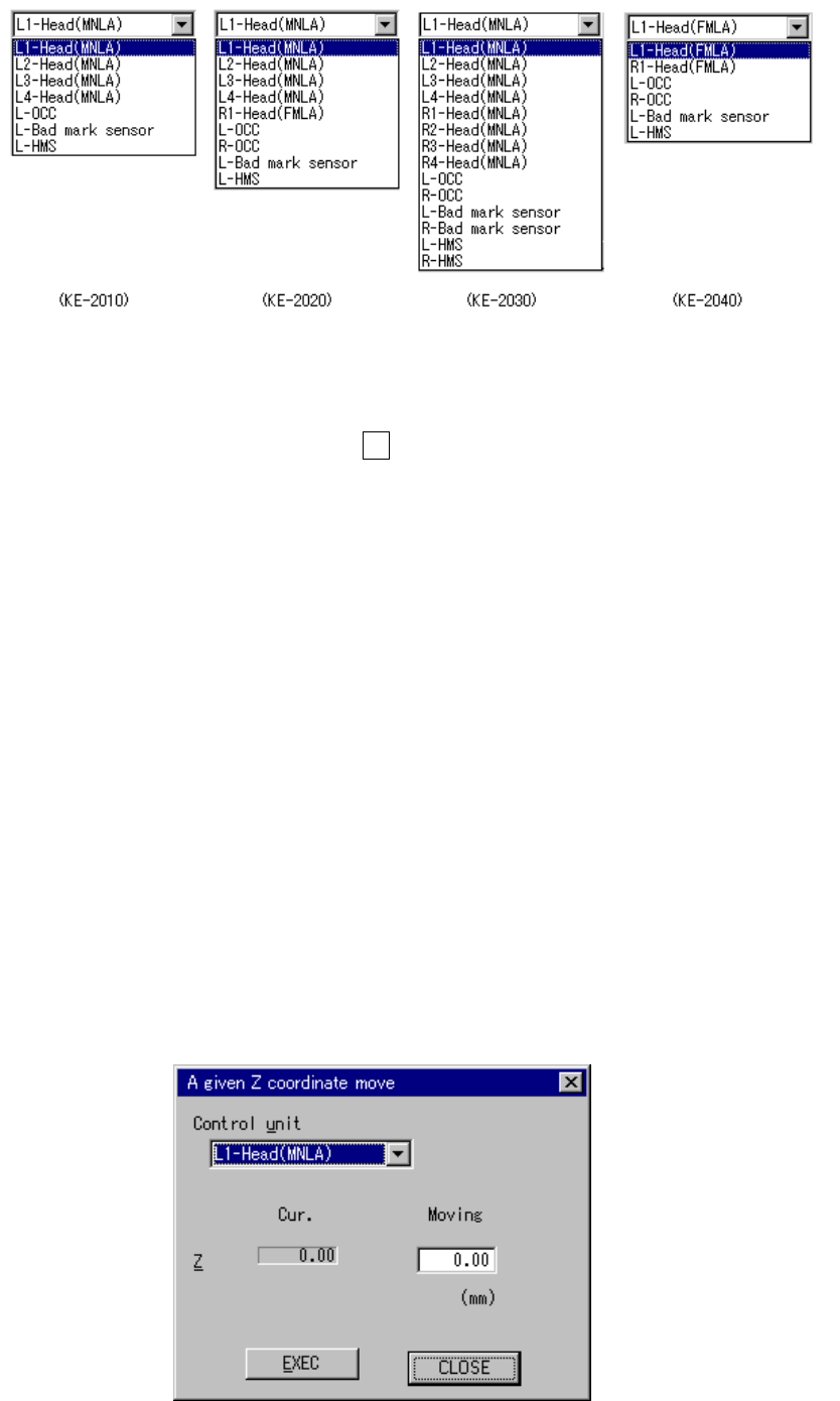
8 − 7
Figure 8.1.7.1 List of the units that can be controlled by each model
When you enter the coordinates to which you want the head to move, then select
the <EXEC> button or press the F3 key, the head moves by referring to the
selected control unit position.
The range of coordinates to be entered varies depending on the unit you
selected.
2) Z move
Moves the selected head to the selected position.
You can move the selected head to the standard position or the desired
coordinates.
As the standard position, you can move the head to one of: laser height,
waiting position, XY axes movable height, VCS height, CVS height, and vacuum
calibration position.
When you select the destination position on the displayed pop-up menu, the
selected head moves to that position.
When you select to move the head to the desired coordinates, the “A given Z
coordinate move” dialog box appears on the screen.
Figure 8.1.8 “A given Z coordinate move” dialog box
8 − 8
Select the unit to be controlled from the combo box.
This selection does not modify the settings on the “Device enable” menu invoked
from the Machine Setup menu: you can select a not-checked (not used) unit.
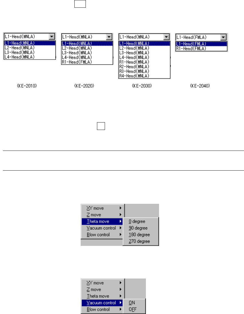
When you press the ALT key while holding the down arrow key, the following list
appears on the screen.
Enter the coordinates to which you want the head to move, and click the
<EXEC> button or press the F3 key. The selected head moves to the specified
coordinates.
Note: Before moving the head, check to see if there is no substance which interferes
with the head at the coordinates you entered in the “Moving” field
3) Theta move
Moves the selected head to the selected position.
4) Vacuum cont.
Sets the vacuum of the selected head to ON or OFF.