KE2010.Instruction Manual.Ver.2.01,Rev.08.pdf - 第607页
8 − 18 8.2.3 Laser control W hen y ou select t he [Head] command on t he [Ctrl] menu, t hen the [Laser cont rol] command, t he following Laser cont rol dialog box appears on t he screen. Figure 8.2.4 Laser control dialog…
8 − 17
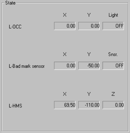
(4) State display
① OCC
The X and Y coordinates and ON and OFF setting of the light are displayed
when the OCC is controlled completely.
② Bad mark sensor
The X and Y coordinates and ON and OFF setting of the sensor are
displayed when the bad mark sensor is controlled completely.
The sensor setting is always displayed.
③ HMS
The X and Y coordinates and Z coordinate are displayed when the HMS is
controlled completely.
8 − 18
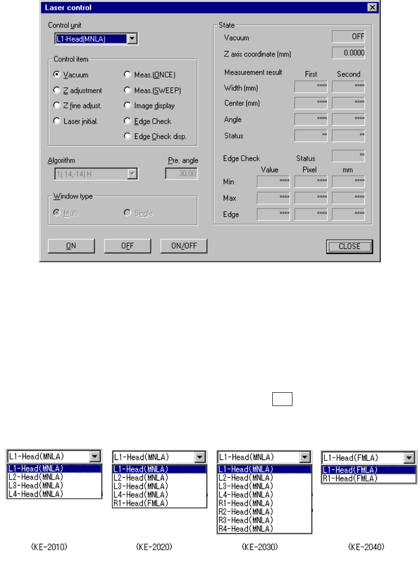
8.2.3 Laser control
When you select the [Head] command on the [Ctrl] menu, then the [Laser control]
command, the following Laser control dialog box appears on the screen.
Figure 8.2.4 Laser control dialog box
(1) Control unit
Select the unit head to be controlled from the combo box.
This selection does not affect the setting of the “Device enable” menu invoked
from the Machine Setup menu. (This means that the not checked units can be
selected.)
The following list appears when you press the ALT key and the down arrow key
at the same time.
8 − 19
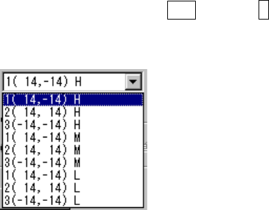
(2) Algorithm
Select the algorithm of the laser control for execution of measurement
(SWEEP), from the combo box.
If you do not select “Meas. (SWEEP)” as the control unit, you cannot set the
algorithm here.
The following list appears when you press the ALT key and ↓ key at the same
time.
The number displayed left to the coordinates indicates the algorithm, and the
alphabet displayed on the right side indicates the theta rotation speed when
“SWEEP” is selected.
Algorithm 1 (14, -14) The machine finds out the position (first time) on which the
component shadow width can be the smallest with rotating
the theta axis from the current position by the pre-load
angle oppositely. Then, it rotates the theta axis 90
degrees from the position where it detected the smallest
shadow width to find out the second smallest shadow width
(second time).
This algorithm is equivalent with the algorithm 1 of the laser
recognition algorithm specified in Component data.
2 (14, 14) The machine finds out the position (first time) on which the
component shadow width can be the smallest with rotating
the theta axis from the current position by the pre-load
angle oppositely. Then, it rotates the theta axis from the
position where it detected the smallest shadow width to find
out the second smallest shadow width (second time).
This algorithm is equivalent with the algorithm 2 of the laser
recognition algorithm specified in Component data.
3 (-14, -14) The system detects the shadow of a component at the
current position without rotating the theta axis (first time).
Then, it detects another shadow with rotating the theta axis
(second time).
This algorithm is equivalent with the algorithm 3 of the laser
recognition algorithm specified in Component data.
Speed H: High M: Medium L: Low