KE2010.Instruction Manual.Ver.2.01,Rev.08.pdf - 第612页
8 − 23 8) Edge Check This item checks to see if t he laser sensor edg e of t he selected head get s dirty or dusty . Mov e the head or nozzle above the laser surf ace, then execute this check . T o execute this check , c…
8 − 22
6) Meas. (SWEEP)
This item executes the laser measurement (SWEEP) of the head selected.
The laser measurement (SWEEP) is the function for detecting the smallest
shadow of a component according to the specified algorithm by rotating the
target component within the detection area. The minimum shadow width
detected for the first time is displayed in the “First” field of the item
“Measurement result”, and that for the second time is displayed in the
“Second” field. (See Figure 8-2-4)
When the control item “Measurement (SWEEP)” is checked, select the
<EXEC>, <LA control> button or press the F3 key or F5 key to control the
measurement.
The measurement result status is updated when the machine finishes
measuring.
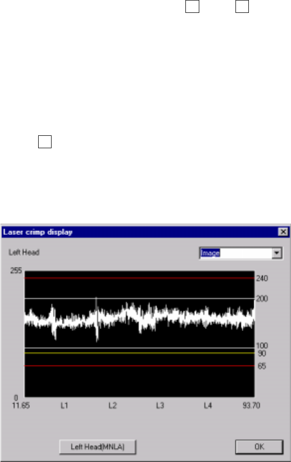
7) Image display
This item displays the image data from the laser sensor of the selected
head.
When the control item “Image display” is checked, click the <EXEC> button
or press the F3 key.
Check to see if the laser level is within the range between 70 and 240, and
each value spreads evenly on the graph. If any value is lowered abruptly or if
any value is extremely low (65 or lower), clean the laser surface side of the
head.
Figure 8.2.5 Image display dialog box
− Laser level value: brightness of laser light transmitted from the
phototransmitter and received with the photoreceptor, that is indicated with
a figure between 0 (darkest) and 255 (brightest).
If a laser head is stained, this value decreases.
8 − 23
8) Edge Check
This item checks to see if the laser sensor edge of the selected head gets
dirty or dusty.
Move the head or nozzle above the laser surface, then execute this check.
To execute this check, click the <ON> button or press the F3 key when the
control item "Edge Check" is checked.
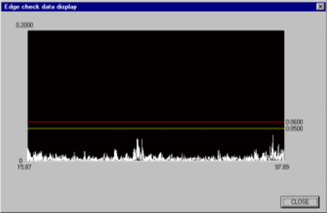
9) Edge check dsp (display)
This item checks to see if the entire laser sensor edge of the selected head
gets dirty or dusty, then displays the check result data.
To execute this operation, select the <ON> button or press the F3 key
when the control item "Edge Check dsp" is checked.
The following shows an example screen displayed when the "Edge Check
dsp" command is executed.
Figure 8.2.6 Edge check data display dialog box
(6) State display
The ON/OFF status of the vacuum of the control head, Z axis coordinate, and
measured results by the laser are displayed when the control has been
completed.

8 − 24
Shown below is the list of status which is returned from laser when the result of the Control
item "Meas. (ONCE)" or "Meas. (SWEEP) is obtained.
Laser status list (1/2)
Status Description
1 Indicates that the selected command is executed successfully.
5 Connection error
This error may be caused due to disconnection or inferior connection of the * cable.
7 This action is required although you do not specify any algorithm. The result is invalid.
8 The sensor is not connected or a hardware error occurs.
10 Sensor error
An unknown hardware error occurs at connection of the coaxial cable of the sensor.
12 Illegal EEPROM version
The software could not check the version of the sensor control module (SCM) EEPROM.
Upgrade the software.
13 Inferior EEPROM data
The SCM EEPROM indicated a data error.
Turn off the power, then restart the system.
14 EEPROM synchronize error
Turn off the power, then restart the system.
15 The input power for operating the machine normally is reduced.
17 The input current is lowered or the output current exceeds the limitation.
60 The length of data set in the communication buffer is shorter than the specified length.
61 The length of data set in the communication buffer is longer than the specified length.
62 The specified length is shorter that the length of the issued command.
63 The specified length is longer that the length of the issued command.
64 A component could not be detected.
65 The frame rate cannot be maintained.
The LA could not recognize input data at the speed required for recognition.
This error occurs when the shade of a component changes frequently or when a component is not
positioned correctly.
67 Interrupt of measurement
Before detecting the minimum width, the LA received a command, so measurement was
interrupted.
70 Algorithm error
The firmware detected the condition which was not assumed to be caused.
75 When an error occurs at the first, second, or third measurement during SWEEP_CMD, the system
stops the process for the second, third or fourth measurement respectively.
This error is notified only when the result of the second, third or fourth measurement is
announced.
77 The contrast of the edge shade obtained with the sensor is not enough to find the edge of a
component correctly.
This error occurs when the shade of a component is not sufficient (when a component does not
cut off laser beam completely).
78 The window parameter which determines a window is below "2000 micron".
79 The entire window is obstructed.
Check to see if there is no foreign substance on the sensor.
80 The left side of the window is obstructed.
Check the component position.
81 The right side of the window is obstructed.
Check the component position.
82 Both sides of the window are obstructed.
Check the component position.