KE2010.Instruction Manual.Ver.2.01,Rev.08.pdf - 第615页
8 − 26 8.3 Transport Sy stem 8.3.1 Transport sy stem individual cont rol W hen y ou select the [ Conveyor] command f rom the [ Ctrl] m enu, then t he [Independent cont rol of conveyor] command, t he following Independent…
8 − 25
Laser status list (2/2)
Status Description
83 Illegal checksum
The software detects an error while it is reading the EEPROM.
Initialize laser.
84 Double start-up
The software detects an error while it is reading the EEPROM.
Initialize laser.
85 There is no EEPROM start-up data.
The software detects an error while it is reading the EEPROM.
Initialize laser.
86 Illegal parameter
An invalid parameter is specified for a command.
Check to see if a correct parameter was entered.
87 Illegal data
Invalid data was detected.
90 An error occurred during calculation of the angle.
91 An error occurred during calculation of the angle.
92 An error occurred during calculation of the angle.
93 The width-angle curve is too flat.
This error occurs when a small component is rotated at very slow speed.
94 An error occurred during calculation of the angle.
95 An error occurred during calculation of the angle.
96 An error occurred during calculation of the angle.
98 Before detecting the minimum width, the angle exceeds the specified limit.
99 The first process (REPORTW_CMD) did not finish before the next minimum width detecting
process (specified with the hold-off angle) started.
100 The required initialization operation was not performed before the information necessary for
initialization was required.
102 The algorithm specified for measurement is invalid.
103 The luminance of laser beam is too low during image check.
104 Illegal image check area
The border of the image check area is not set correctly.
105 Image check failure
The image check function failed to compare parameters.
106 An error which is not defined with any of the currently specified error levels occurred. Change the
error level.
The results of the error check are shown below:
Min: indicates the lowest luminance of the sensor
Max: indicates the highest luminance of the sensor
Edge: indicates the highest edge check value and the corresponding position
obtained when you performed the edge check.
For the MNLA sensor, "0.045" is a guideline of dirtiness. If a value higher
than 0.045 is displayed here, clean the sensor.
Note: The edge check value indicates a substituted characteristic value which
shows a laser centering error. The larger the edge check value becomes, the
more the centering error increases: this is normally caused by the soiled
window.
¬
8 − 26
8.3 Transport System
8.3.1 Transport system individual control
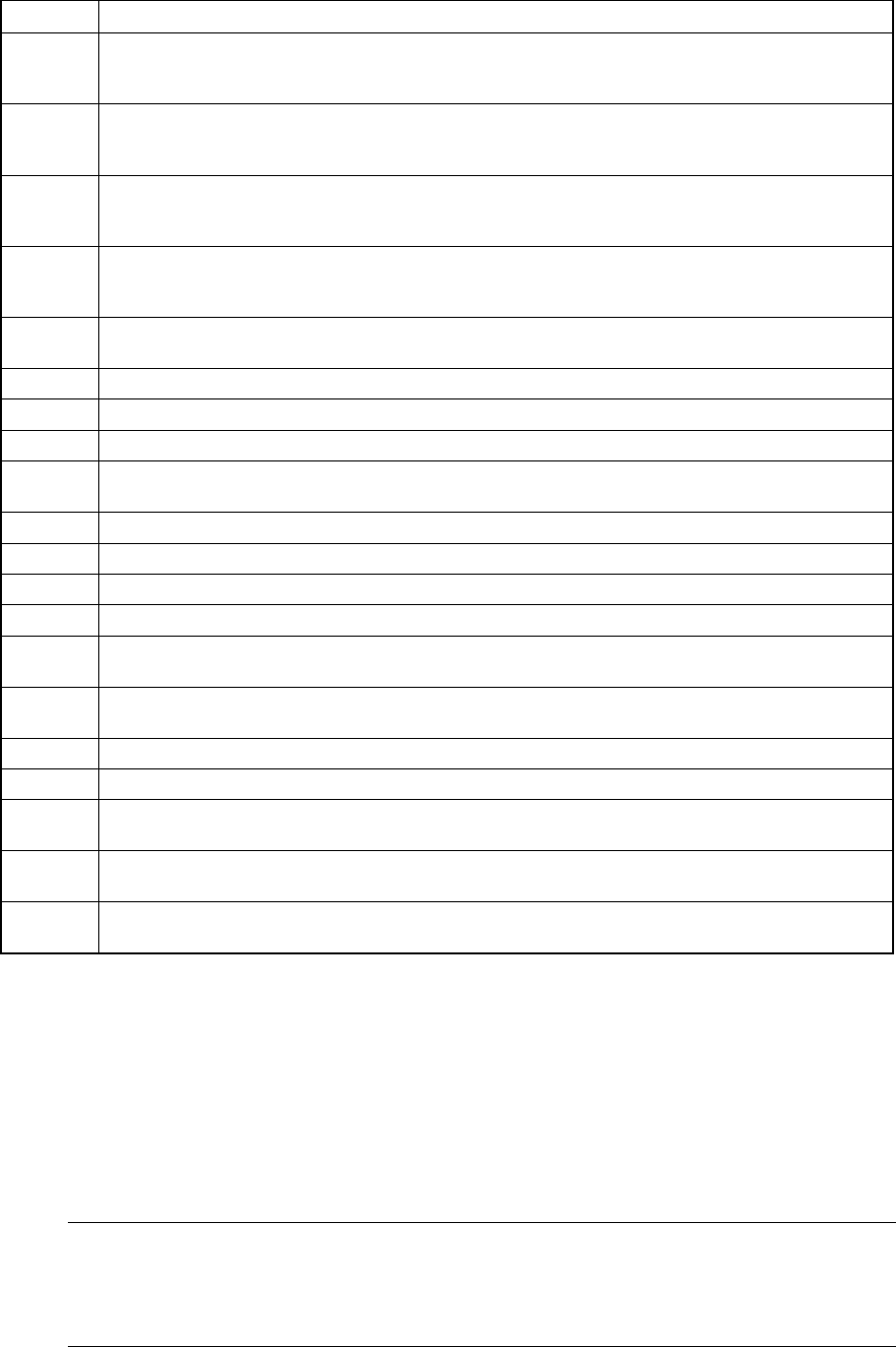
When you select the [Conveyor] command from the [Ctrl] menu, then the
[Independent control of conveyor] command, the following Independent control of
conveyor dialog box appears on the screen.
Figure 8.3.1 Independent control of conveyor dialog box
(Screen example when a KE-2030 is used)
Note: *1 displayed with a KE-2030 only.
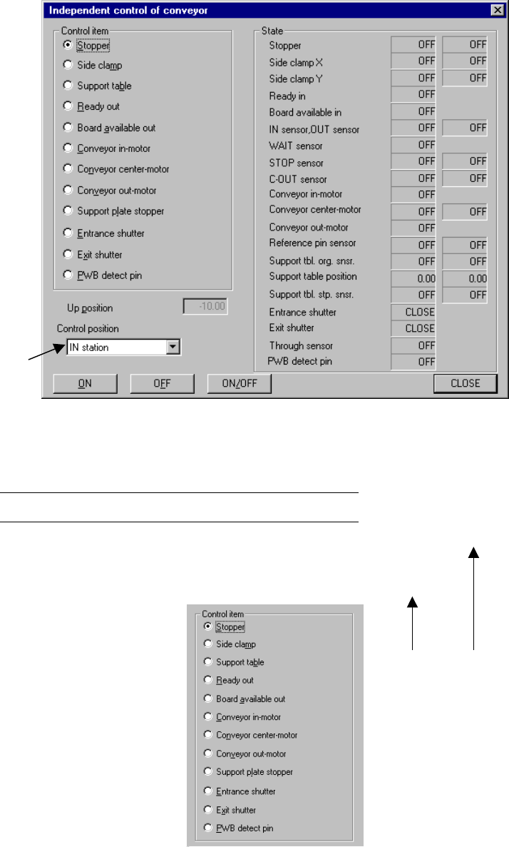
(1) Control item
Select a control item with the corresponding radio button.
*1
*1
IN station OUT station
8 − 27
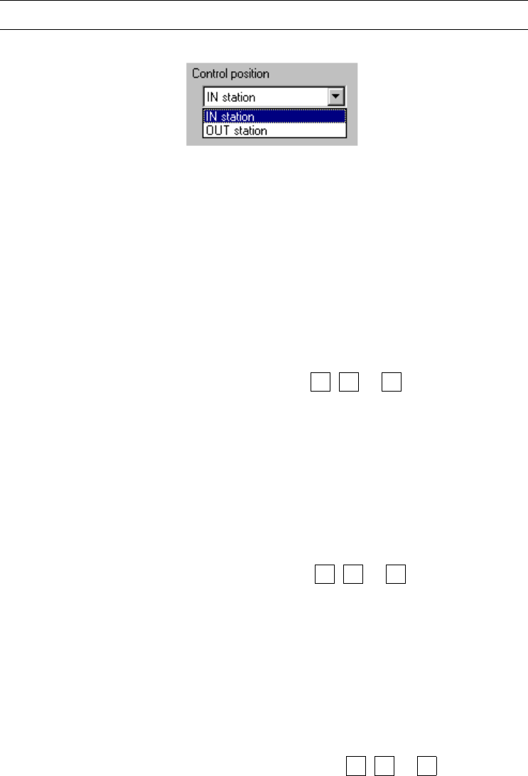
(2) Control position
With the combo box, select the position when the conveyor is automatically
controlled.
You cannot select the control position if the control item, “Ready out”, “Board
available out”, “Conveyor in-motor” or “Conveyor out-motor” is selected.
Note: You cannot select this menu item for models other than a KE-2030.
(3) Control button
Execute the selected control item with the control buttons.
The displayed control buttons vary depending on the control item you selected.
1) Stopper
This item turns on and/ off the stopper .
− When the control item “Stopper” is checked, select the <ON>, <OFF> or
<ON/OFF> button or press the F3, F4 or F5 key to control the stopper
pin.
− The status display is updated when the control is completed.
2) Side clamp
This item turns on and/ or off the side clamp cylinder.
− The control item “Side clamp” is checked, click the <ON>, <OFF> or
<ON/OFF> button, or press the F3, F4 or F5 key.
− The state display is updated when the side clamp cylinder is controlled
completely.
3) Support plate
This item moves up and/or down the support plate.
− The control item “Support plate” is checked, click the <UP>, <DOWN>
or <UP/DOWN> button or press the F3, F4 or F5 key.
− The state display is updated when the support plate is controlled
completely.