KE2010.Instruction Manual.Ver.2.01,Rev.08.pdf - 第653页
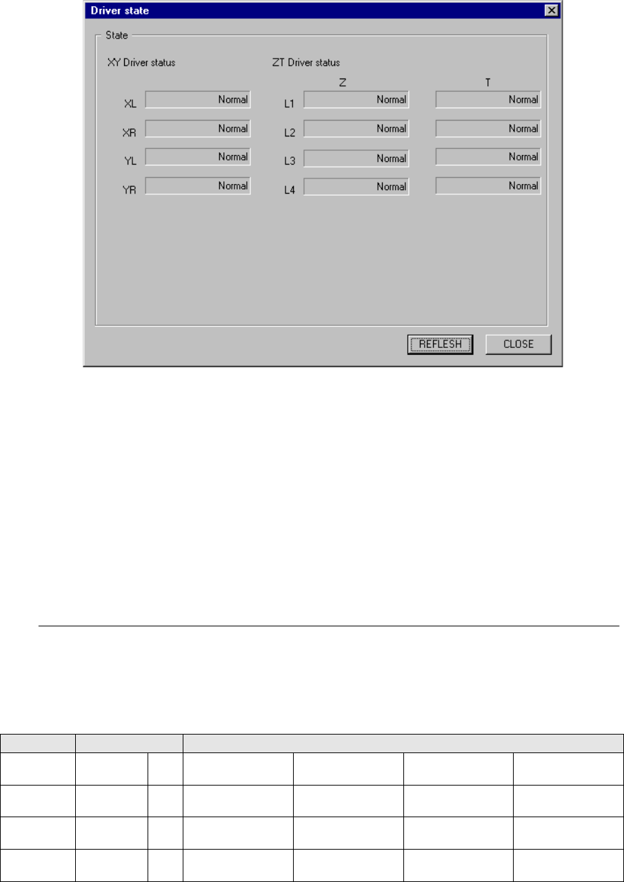
8 − 64 8.6.7 Driv er state W hen y ou select the [ Driver state] com mand on the “O thers” menu that is invoked fr om the [Ct rl] comm and, the f ollowing “Driver stat e” dialog box appears on the screen. Figure 8.6.7 “D…
8 − 63
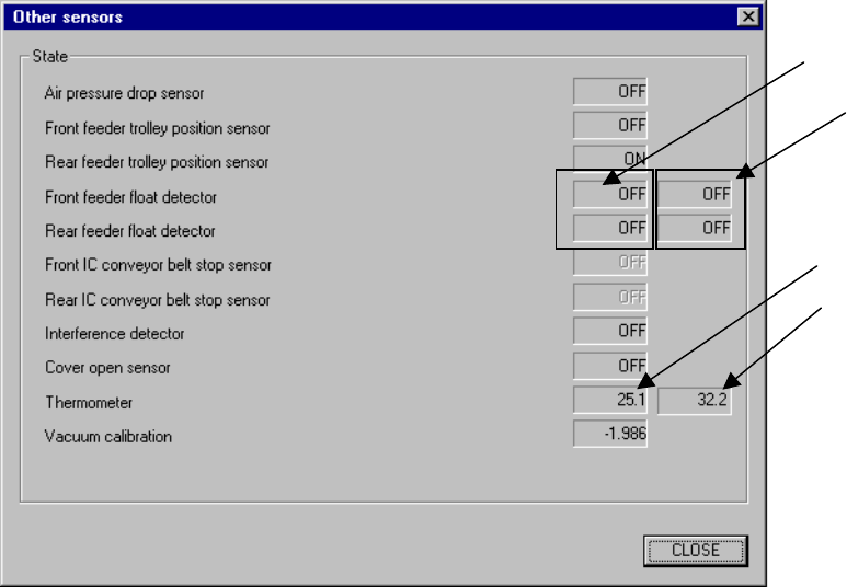
8.6.6 Other sensors
When you select the [Others] command on the [Ctrl] menu, then the [Other sensors]
command, the following Other sensors dialog box appears on the screen.
Figure 8.6.6 Other sensors dialog box
(1) State display
This displays the status of each sensor.
- This function does not affect the setting of the “Device enable” menu invoked
from the Machine Setup menu: this means that you can display the state of
a not-checked (not used) unit.
The state display of the sensors will be performed by continually reading and
displaying the status.
Front
Rear
Upper (VCS*)
available with a
KE-2020/2040 only.
Upper (X-axis)
8 − 64
8.6.7 Driver state
When you select the [Driver state] command on the “Others” menu that is invoked
from the [Ctrl] command, the following “Driver state” dialog box appears on the
screen.
Figure 8.6.7 “Driver state” dialog box (displayed with a KE-2010)
(1) State display
This section displays the status of each axis.
The system displays “***” in the column for an axis that is set to “Not used” on
the “Device enable” screen that is invoked from the Machine Setup menu.
The system displays one of the following types of status for each axis: Normal,
Over current, Over load, Voltage limit over, EEPROM Err, Over heating, Encoder
Err and CPU Err.
When you click the <REFLESH> button, the system obtains the status of each
axis again, and then updates the corresponding status.
− If the system detects one of the errors: Voltage limit over, EEPROM Err, Over
heating and CPU Err, it cannot judge which axis generates the corresponding
error. Therefore, the axes described below are put in the same status.
Table 8.7.1 Combination of axes sharing the CPU
Model X and Y axes Z and T axes
KE-2010
XL, XR,
YL, YR
Z and T axes of the
heads L1 and L2
Z and T axes of the
heads L3 and L4
KE-2020
XL, XR,
YL, YR
Z and T axes of the
heads L1 and L2
Z and T axes of the
heads L3 and L4
Z and T axes of the
R1 head
KE-2030
XL, XR,
YL, YR
Yc
Z and T axes of the
heads L1 and L2
Z and T axes of the
heads L3 and L4
Z and T axes of the
heads R1 and R2
Z and T axes of the
heads R3 and R4
KE-2040
XL, XR,
YL, YR
Z and T axes of the
heads L1
Z and T axes of the
heads R1
8 − 65
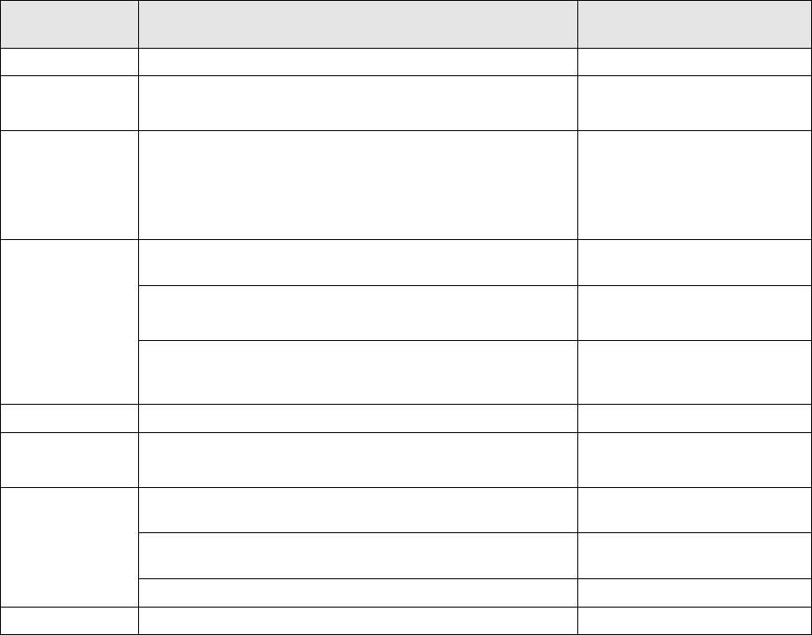
◇ Each displayed status, its description and cause are shown in the table below.
Table 8.7.2 Description and cause of each status
Displayed
status
Description Cause
Normal The corresponding axes function normally.
Over current
The system found that the current supplied to the motor
exceeded the regulated value.
- Short circuit in the motor
- Motor rare short
Over load
The system found that the average current supplied to the
motor exceeded the regulated value.
– Axis locked
– Motor cable is broken.
– Overload operation
– Break failure
The system found that the number of motor rotations
exceeded the set value.
– Encoder error
The system found that excess voltage was placed on the
power supply that drove the motor.
– Regeneration error
– Excessive input voltage
Voltage limit
over
The system found that the servo ON signal was input and
the current driving the motor decreased below the
regulated value.
– Input voltage error
– A break in the power supply
EEPROM Err The system found that the EEPROM malfunctioned. – Driver error
Over heating
The system found that the temperature of the heat sink
was raised abnormally.
– Overload
– Ambient temperature rise
The system detected that the line driver output of the motor
encoder was not connected to the system.
– Break in the encoder
The system detected the commutation signal error of the
motor encoder.
– Encoder error
Encoder Err
The system detected the encoder output error at power-on. – Wiring failure
CPU Err The system found that the CPU malfunctioned. – CPU error