KE2010.Instruction Manual.Ver.2.01,Rev.08.pdf - 第658页
9 − 4 9.2.3 Warming-up operation During warming- up, a screen shown below appears. Figure 9.2. 3.1 "Under warm-up" dialog box (1) Ax is The X, Y Z and theta axes mot ors and the AT C slide plate operat e. Note …

9 − 3
(2) Setting the pause time and number of times
- Set the time spent for stopping warming-up operation and the number of times
you are to perform warming-up operations.
- The available values vary depending on the warming-up operation terminating
conditions.
- Time: 0 to 9999 (minutes)
Note: When "0" is set, warming-up operation will not finish until you suspend it.
- Number: 1 to 999999
− Initial value: 0
(3) Setting the condition for terminating warming-up operation
- Select the condition for terminating warming-up operation: Time or Number.
− Initial setting: Time
(4) Setting the speed
- Set the speed of an axis.
- You can select high speed (High) or middle speed (Middle).
− Initial setting: Middle
Note: The axis speed is fixed to “Middle” for the standard specifications
(see Figure 10.2.2.1.)
Contact us or your dealer for the details on the speed setting (variable).
9 − 4
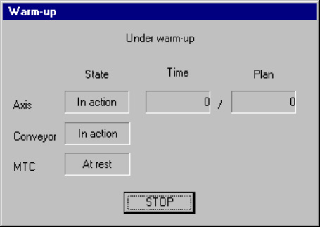
9.2.3 Warming-up operation
During warming-up, a screen shown below appears.
Figure 9.2.3.1 "Under warm-up" dialog box
(1) Axis
The X, Y Z and theta axes motors and the ATC slide plate operate.
Note that warming-up operation finishes when the ATC slide plate opens and
closes ten times.
(2) Conveyor
The PWB transfer motor, back-up table, stopper pin, edge reference cylinder
(option), and PWB check cylinder (only for a KE-2030) operate.
Note that warm-up operation finishes when each of the stopper pin, edge
reference cylinder and PWB check cylinder turns on, then off four times.
(3) MTC
The shuttle operates.
− When you press the <STOP> switch or click the <STOP> button displayed on
the dialog box above, the confirmation dialog box appears on the screen.
When you click the <Yes> button, warming-up operation terminates.
When you click the <No> button, warming-up operation restarts.
9 − 5
9.3 Idle Conveyor
Use this command when you transport a PWB through this machine as a PWB
transportation buffer.
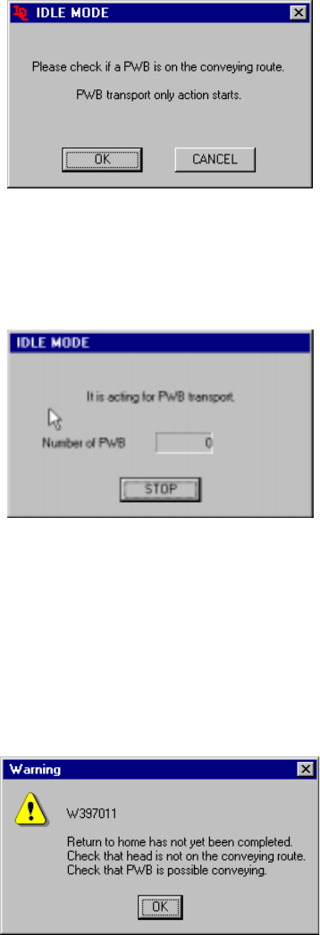
When you select the [Idle Conveyor] command on the [Maintenance] menu invoked
from the menu bar of the main menu, the following "IDLE MODE" initial screen
appears.
Figure 9.3.1 Initial screen
- When you click the <OK> button, the machine starts operating as a PWB
transportation buffer and the following screen appears.
Figure 9.3.2 "IDLE MODE-to act for PWB transport" dialog box
- When you click the <STOP> button, the machine stops acting as a PWB
transportation buffer.
− If the system has not returned to the home position yet at start-up, the following
confirmation message appears on the screen.
Figure 9.3.3 Not returned to home position confirmation message
If the message above appears on the screen, manually move the head to outside the
PWB transport path, and push down the support table. Check to see if a PWB can
be transported.