KE2010.Instruction Manual.Ver.2.01,Rev.08.pdf - 第659页
9 − 5 9.3 Idle Convey or Use this command when you transport a PW B through this machine as a PW B transport ation buff er. W hen y ou select t he [Idle Conveyor] command on t he [Maintenance] menu invoked fr om the menu…
9 − 4
9.2.3 Warming-up operation
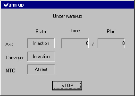
During warming-up, a screen shown below appears.
Figure 9.2.3.1 "Under warm-up" dialog box
(1) Axis
The X, Y Z and theta axes motors and the ATC slide plate operate.
Note that warming-up operation finishes when the ATC slide plate opens and
closes ten times.
(2) Conveyor
The PWB transfer motor, back-up table, stopper pin, edge reference cylinder
(option), and PWB check cylinder (only for a KE-2030) operate.
Note that warm-up operation finishes when each of the stopper pin, edge
reference cylinder and PWB check cylinder turns on, then off four times.
(3) MTC
The shuttle operates.
− When you press the <STOP> switch or click the <STOP> button displayed on
the dialog box above, the confirmation dialog box appears on the screen.
When you click the <Yes> button, warming-up operation terminates.
When you click the <No> button, warming-up operation restarts.
9 − 5
9.3 Idle Conveyor
Use this command when you transport a PWB through this machine as a PWB
transportation buffer.
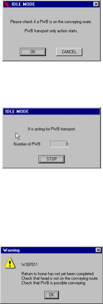
When you select the [Idle Conveyor] command on the [Maintenance] menu invoked
from the menu bar of the main menu, the following "IDLE MODE" initial screen
appears.
Figure 9.3.1 Initial screen
- When you click the <OK> button, the machine starts operating as a PWB
transportation buffer and the following screen appears.
Figure 9.3.2 "IDLE MODE-to act for PWB transport" dialog box
- When you click the <STOP> button, the machine stops acting as a PWB
transportation buffer.
− If the system has not returned to the home position yet at start-up, the following
confirmation message appears on the screen.
Figure 9.3.3 Not returned to home position confirmation message
If the message above appears on the screen, manually move the head to outside the
PWB transport path, and push down the support table. Check to see if a PWB can
be transported.

9 − 6
9.4 Machine Management Information
When you select the [Maintenance] command on the menu bar, then the [Device
Management Information] command on the Maintenance menu, it allows you to select
any of the following operation information items.
9.4.1 Machine operation information
When you select the [Window] command on the menu bar, then the [Machine
Operation Information] command on the displayed menu, a screen shown in Figure
9.4.1.1 or 9.4.1.2 appears.
No. Item Description
1 Number of produced
PWBs
Total number of PWBs produced after the machine starts collecting data.
This number is counted independently of a production program.
2 Production number
(circuit)
Total number of PWBs produced after the machine starts collecting data.
This number is updated when one PWB is produced completely, and does not
include the number of circuits on which a bad mark was detected (does not
include PWBs whose production was interrupted halfway either).
3 Ratio of Pick-up Component picking ratio (%)
([Number of picked components] / [Number of picked components] + [Number
of Pick-up errors]) x 100 (%)
4 Ratio of Placement Machine placing ratio (%)
([Number of picked components] / [Number of picked components] + [Number
of Pick-up errors]) x 100 (%)
5 Ratio of Operation Machine operating ratio (%)
[Operation time] / [Number of picked components] + [Number of Pick-up
errors]) x 100 (%)
6 Ratio of Retry 100 - (Ratio of Pick-up)
7 Power supply ON time Total time passed since power-on or the machine starts collecting data
8 Operation time Total time spent in producing PWBs since the machine starts collecting data
This time represents the time spent in picking and placing components (and
also discarding them).
9 Preparation time to drive Total time for which the machine does not produce any PWB such as time
spent in editing data.
[Power supply ON time] - [Operation time]
[Conveyor waiting time]
[Stop time caused by Out-of-Component]
[Maintenance stop time]
[Stop time caused by trouble]
10 Conveyor waiting time Total of the time durations from when the system started transporting a PWB
to when it finished transporting it.
11 Carry in waiting time Total of the time durations from when the system became able to send in a
PWB to when the next PWB was clamped.
12 Carry out waiting time Total of the time durations from when the clamped PWB was released to
when the PWB was stored onto the OUT buffer. However, it does not include
the time duration spent for an operation performed to eject a PWB only.
13 Maintenance stop time Total time for which the machine pauses in response to user request
14 Stop time caused by
trouble
Total time for which the machine pauses due to an error.
15 Stop time caused by
Out-of-Component
Total time for which the machine stops because the stocked components run
out.
16 Number of picked
components
Total number of times the machine picked components successfully (This
number is counted independently of a production program/component supply
device.)
17 Number of placed
components
Total number of times the machine placed components successfully (This
number is counted independently of a production program/component supply
device.)
18 Number of Pick-up
errors
Total number of times a picking error occurred (This number is counted
independently of a production program/component supply device.)
A chip rise error or recognition error is not counted.