KE2010.Instruction Manual.Ver.2.01,Rev.08.pdf - 第68页
2 − 5 Key na me Function WI N D O W • Switches the cur sor dis played on the vision monitor f rom the cros s-hair cursor to the window cursor, and switches the teac hing m ode also, then the LED lights. PREVIOUS • Moves …
2 − 4
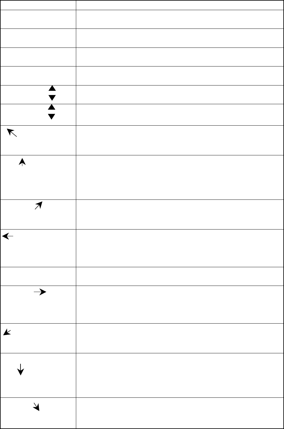
Table 2.1.2 List of HOD keys and their functions
Key name Function
F1 • Assigns the X-Y axes after a device is selected.
• Selects another axis or specifies the number of points during teaching.
F2 • Assigns the Z axis after a device is selected.
• Selects another axis or specifies the number of points during teaching.
F3 • Assigns the θ axis after a device is selected.
• Selects another axis or specifies the number of points during teaching.
F4 • Assigns an axis after a device is selected.
• Selects another axis or specifies the number of points during teaching.
No
• Increments or decrements the number for selecting an axis.
• Specifies the axis number displayed on the LCD.
DEVNAME
• Increments or decrements a device number to be selected.
• Specifies the device number displayed on the LCD.
-X+Y
<When XY is selected> Moves the X-Y axes to the direction indicated with the
arrow mark.
<When CAMERA is selected> Moves the cursor to the direction indicated
with the arrow mark.
+Z+Y
<When XY is selected> Moves the X-Y axes to the direction indicated with the
arrow mark.
<When CAMERA is selected> Moves the cursor to the direction indicated
with the arrow mark.
<When the Z axis is selected> Moves the Z axis to the direction indicated
with the arrow mark.
-X+Y
<When XY is selected> Moves the X-Y axes to the direction indicated with the
arrow mark.
<When CAMERA is selected> Moves the cursor to the direction indicated
with the arrow mark.
-θ-X
<When XY is selected> Moves the X-Y axes to the direction indicated with the
arrow mark.
<When CAMERA is selected> Moves the cursor to the direction indicated with
the arrow mark.
<When the θ axis is selected> Moves the theta axis to the desired angle.
FAST • Moves the axis at high speed.
• When selected, its LED lights.
+θ+X
<When XY is selected> Moves the X-Y axes to the direction indicated with the
arrow mark.
<When CAMERA is selected> Moves the cursor to the direction indicated with
the arrow mark.
<When the θ axis is selected> Moves the theta axis to the desired angle.
-X-Y
<When XY is selected> Moves the X-Y axes to the direction indicated with the
arrow mark.
<When CAMERA is selected> Moves the cursor to the direction indicated
with the arrow mark.
-Z-Y
<When XY is selected> Moves the X-Y axes to the direction indicated with the
arrow mark.
<When CAMERA is selected> Moves the cursor to the direction indicated
with the arrow mark.
<When the Z axis is selected> Moves the Z axis to the direction indicated
with the arrow mark.
+X-Y
<When XY is selected> Moves the X-Y axes to the direction indicated with the
arrow mark.
<When CAMERA is selected> Moves the cursor to the direction indicated
with the arrow mark.
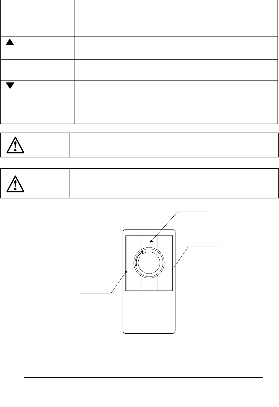
2 − 5
Key name Function
WINDOW • Switches the cursor displayed on the vision monitor from the cross-hair
cursor to the window cursor, and switches the teaching mode also, then
the LED lights.
PREVIOUS
• Moves the cursor to the previous data.
PAUSE • Temporarily halts the placement tracking operation.
CANCEL • Cancels the data obtained through teaching.
NEXT
• Moves the cursor to the next data.
ENTER • Validates the data entered through teaching.
CAUTION
When connecting the HOD unit the machine, make sure that the
machine has been turned OFF.
CAUTION
The magnet sheet is pasted on the rear of the HOD unit. Keep a floppy
disk away from the HOD because the data stored on the disk may be
erased.
2.1.3 Track ball
Figure 2.1.3
Note 1: Do not click the middle section of a trackball since any key may not be
accepted depending on your clicking timing.
* Cleaning a ball
Turn clockwise the section which clamps a ball to remove a ball.
Right button
Left button
Note 1
2 − 6
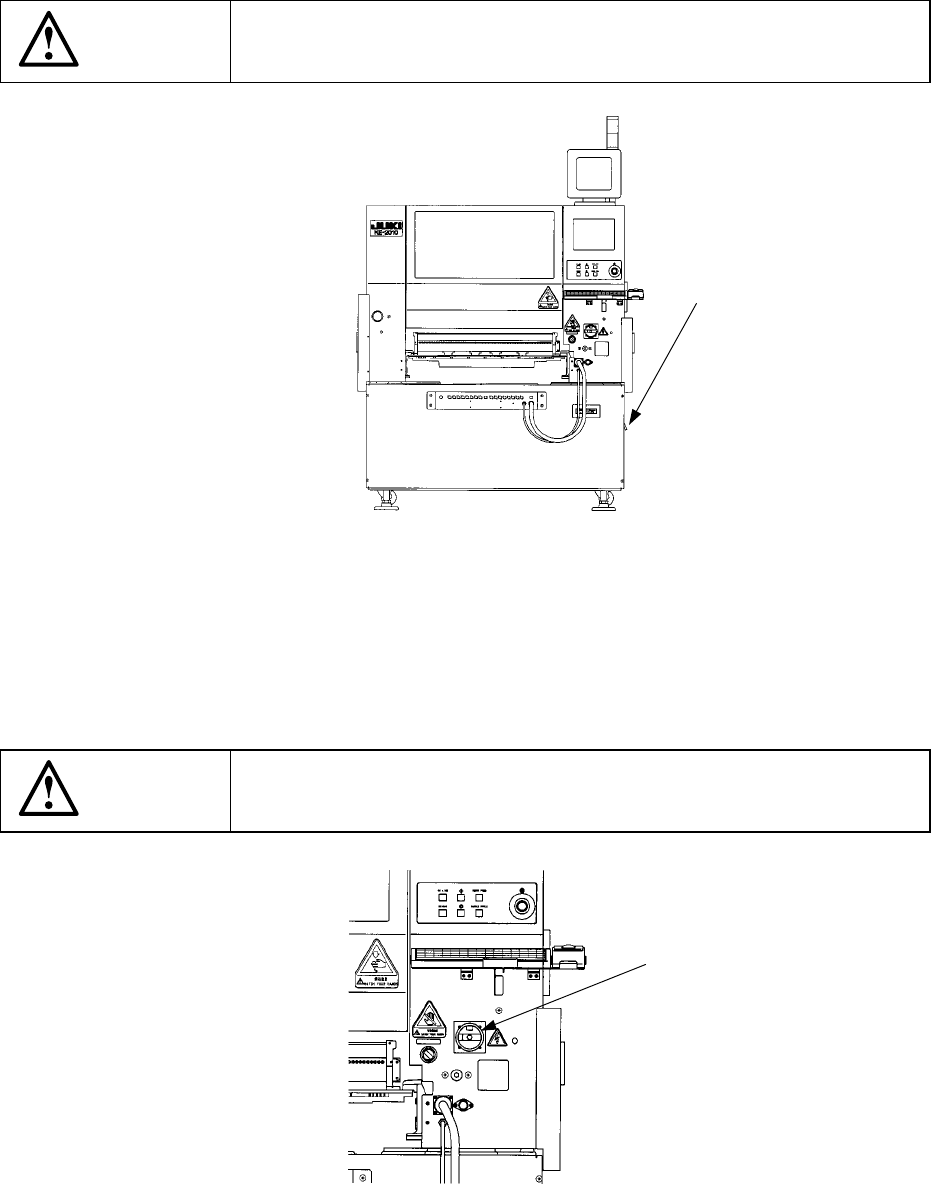
2.1.4 No-fuse breaker
As shown in Figure 2.1.4, the no-fuse breaker is found on the lower right side of the
machine with viewed from its front. Normally raise the lever (to ON status).
This switch functions as a circuit breaker, so it cuts off the power automatically if the
overcurrent is supplied to the machine.
CAUTION
Do not turn off the no-fuse breaker when the main switch is turned on.
Figure 2.1.4 Front of the main unit
2.1.5 Main switch
As shown in Figure 2.1.5, the main switch is found on the upper front cover on the
front right side of the machine. This switch is turned off when set horizontally, and
on when vertically.
CAUTION
Do not turn on the main switch when the no-fuse breaker is turned off.
Figure 2.1.5 Front right side of the main unit
No-fuse breaker
Main switch