KE2010.Instruction Manual.Ver.2.01,Rev.08.pdf - 第684页
9 − 30 9.6.3 Saving Click the < OK> but ton on the “Machine Data Save” dialog box. To close this dialog box without saving any data, click the <Cancel> butt on. Figure 9.6.3 “Machine Data Save” di alog box Th…
9 − 29
9.6 Saving the Machine Information
This function allows you to save the information required to analyze an error onto the
hard disk as a batch operation.
Use this function only if an error occurs at the machine.
9.6.1 Starting up from the menu invoked from the “Production” screen
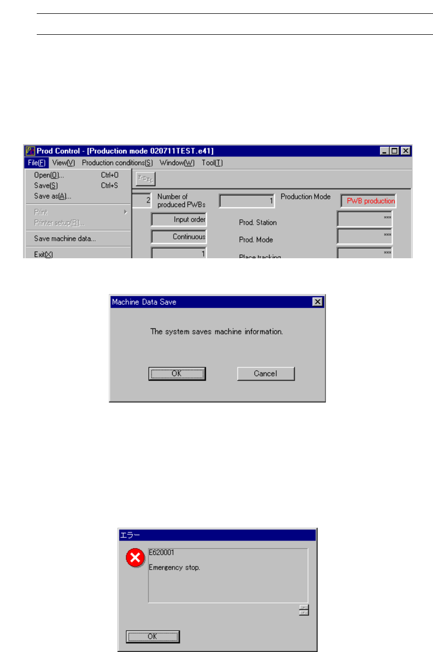
Select the [Save machine data] command on the “File” menu invoked from the
“Production” screen.
The “Machine Data Save” dialog box appears on the screen.
Figure 9.6.1.1 Selecting the [Save machine data] command
Figure 9.6.1.2 “Machine Data Save” dialog box
9.6.2 Starting up from the “Emergency stop” screen
Press the [F9] key of a keyboard when the “Emergency stop” screen is displayed.
The “Machine Data Save” dialog box appears on the screen in the manner described
above also.
Figure 9.6.2 “Emergency stop” screen
9 − 30
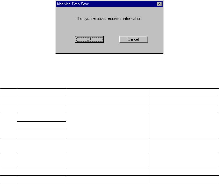
9.6.3 Saving
Click the <OK> button on the “Machine Data Save” dialog box.
To close this dialog box without saving any data, click the <Cancel> button.
Figure 9.6.3 “Machine Data Save” dialog box
This function saves the following files onto the hard disk.
No. File name Description Remark
1 Computer name.log
Log of the machine operations −
2 hist.txt Operation history −
AppEvent.Evt
SecEvent.Evt
3
SysEvent.Evt
Windows NT event log −
4 drwtsn32.log Dr. Watson log This file is saved only if a Dr.
Watson error occurs.
5
process.txt Information on which process is being
stated up currently
−
6
cnvrstat.txt Conveyor sensor condition −
7
axispos.txt Current head position −
Table 9.6.3 Files to be saved with the [Save machine data] command
10 − 1
CHAPTER 10 SELF CALIBRATION
10.1 Overview
The items set for self-calibration are shown in Table below:
Note that a person who can set the following items is restricted as described under
Section 11.2 "User Group Setting".
Before you register the user group, be sure to contact our Technical Service
department.
Table 10.1.1 Self-calibration Items
No. Self-calibration group Description
1 Correct coefficient of XY axis Correction parameter for the XY axes stop accuracy
2 Laser sensor height Height of the laser sensor viewed from the top of a board
3 Rotation center of noz. Center of the nozzle rotation detected with the laser sensor
4 Head offset Assembling position of each head relative to the OCC
Assembling angle of the laser alignment unit relative to the main
unit
5 VCS offset VCS camera assembling position
6 VCS binary-coded threshold
level
Binary-coded threshold when recognized by the VCS (threshold
level)
7 Vacuum calibration Vacuum calibration value
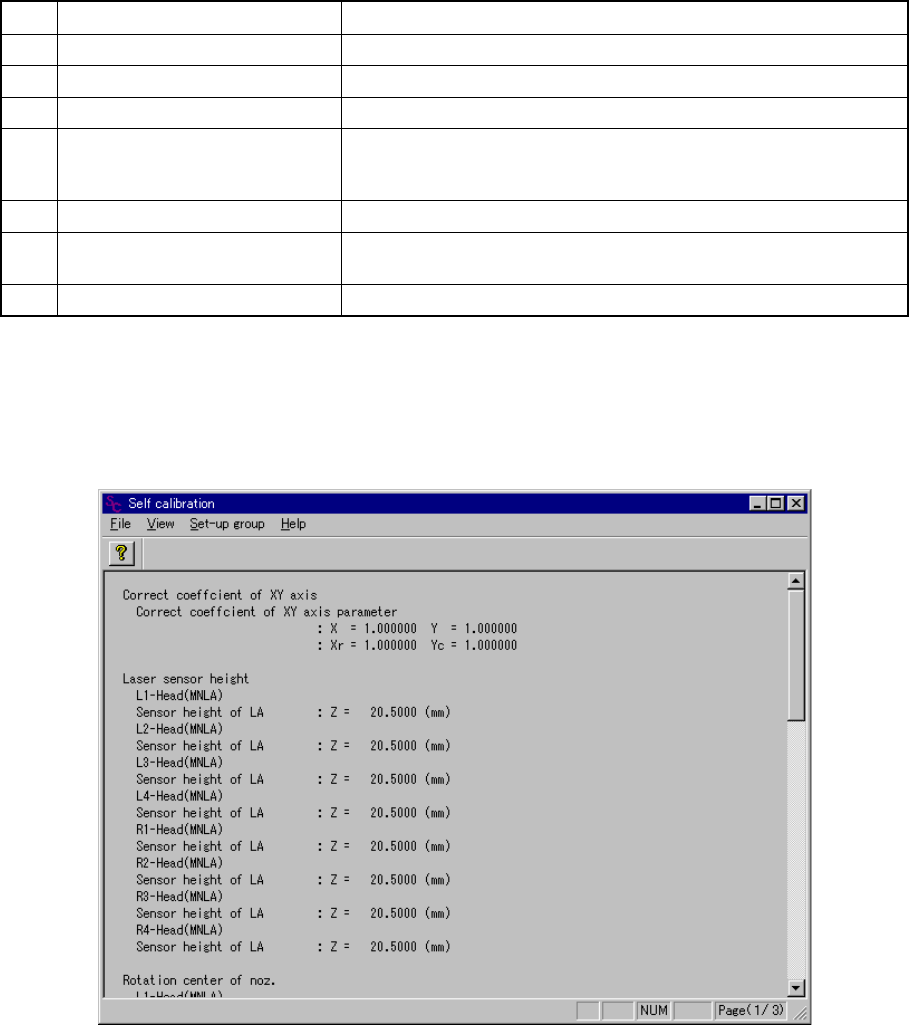
(1) Screen displayed immediately after start-up
When you select the [Self-calibration] command on the [Setup] menu, the
following ”Self calibration” initial screen appears.
Figure 10.1.1 Self calibration initial screen
(Screen example when a KE-2030 is used)