KE2010.Instruction Manual.Ver.2.01,Rev.08.pdf - 第736页
12 − 6 12.5 Installing the M atrix Tray Changer (M TC) CA UTION To avoid any accident caused by sudden activat ion of the machine, turn off the power. Figure 12.5.1 1) Move the MTC main unit 4 f rom t he rear so that the…

12 − 5
12.4 Procedure for Mounting the Matrix Tray Holder on the Feeder
Bank (See Figure 12.4.1.)
CAUTION
To avoid any accident caused by sudden activation of the machine,
turn off the power.
1) Grip the side plate ① and lock lever ② to open the lock holder ③.
2) Insert the front pin ④ into the fixing plate of the rear bank.
3) Release the side plate ① and lock lever ② when the front plate ⑤ into which
the pin ④ is inserted is in contact with the fixing plate, then lock these plates with
the lock holder ③.
4) To detach the matrix tray holder, follow this procedure in the reverse order.
① Side plate
② Tray lock lever
③ Lock holder
④ Pin
⑤ Front plate
Figure 14.4.1
CAUTION
To prevent your body from injury and to avoid damage to the machine,
mount a tray on the matrix tray holder only after you remove the matrix
tray holder from the feeder bank or after you check to see if the main
unit completely stops.
If you mount a tray on the matrix tray holder although the matrix tray
holder is being installed on the feeder bank, be sure to check your
environment before mounting a tray so that the machine cannot start
unexpectedly when another operator operates the machine by mistake.
Reference pin
Fixing plate
12 − 6
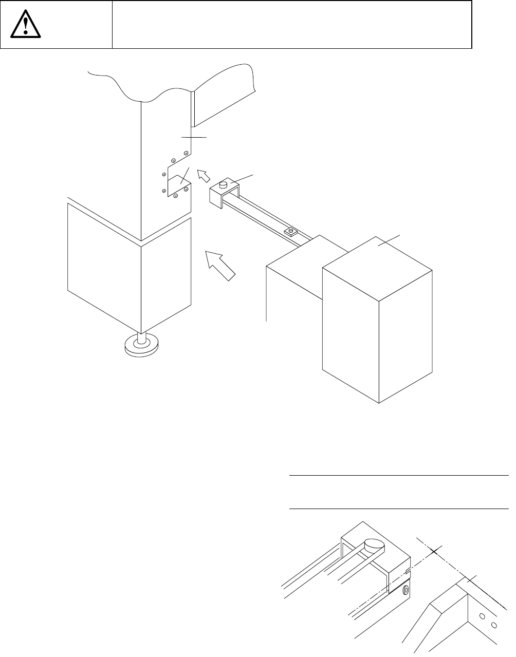
12.5 Installing the Matrix Tray Changer (MTC)
CAUTION
To avoid any accident caused by sudden activation of the machine,
turn off the power.
Figure 12.5.1
1) Move the MTC main unit 4 from the rear
so that the MTC shuttle section 3 can be
inserted under the MTC guide cover 1
which is located on the right far side with
viewed from the front of the main unit.
2) Slide the MTC main unit 4 toward the
cover RUR 2 as close as possible, then
install the MTC.
3) Adjust the adjuster foot of the MTC main
unit so that the shuttle tip cut-out can
be located at a height of the top side of
the fixing plate.
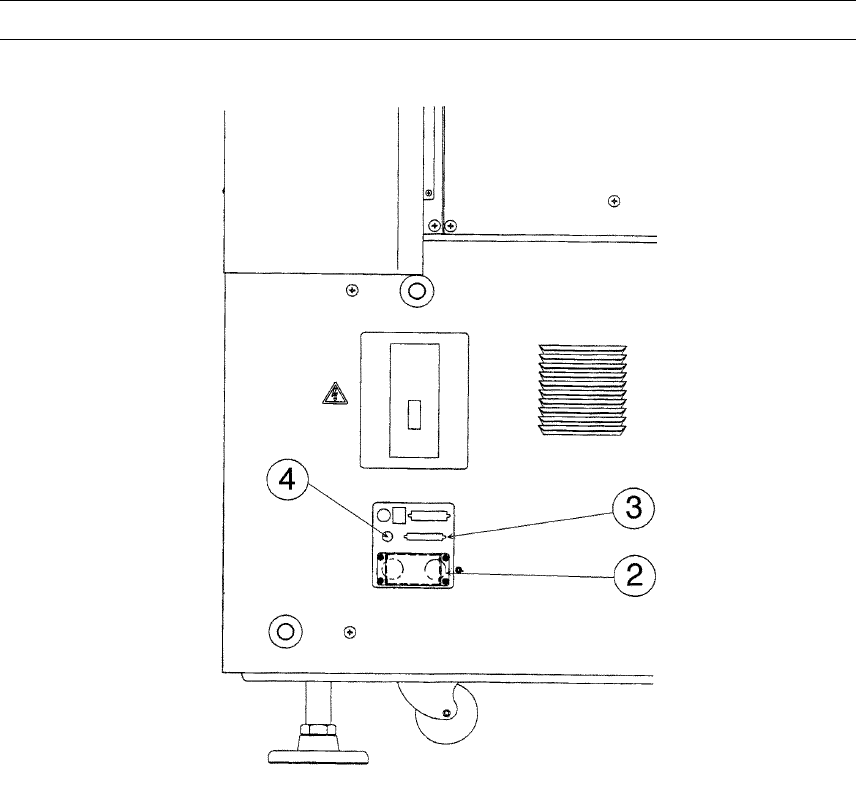
Figure 12.5.2 A arrow-view figure
① MTC guide cover
② Cover RUR
③ MTC shuttle section
④ MTC main unit
⑤ Front plate
①
②
③
④
←
←←
←A
REAR 79
Note: Refer to the supplied Instruction
Manual for how to operate an MTC.
12 − 7
4) Connect the MTC power plug ② and signal connector ③ to the corresponding
jack/connector and the air tube to the MTC air fitting of the interface panel located
on the right side of the main unit.
Note: Be sure to use the cable and air tube supplied with the MTC.
Figure 12.5.3
② MTC power jack
③ MTC interface connector
④ MTC φ 6 tube inlet