KE2010.Instruction Manual.Ver.2.01,Rev.08.pdf - 第737页
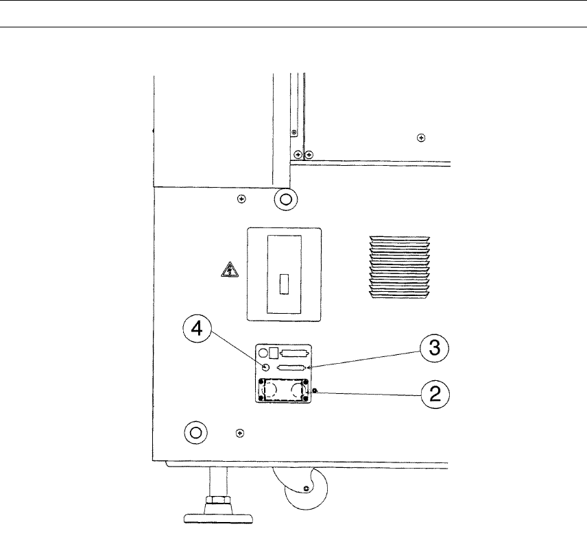
12 − 7 4) Connect the MTC power plug ② and sig nal connector ③ to the cor responding jack/ connector and t he air tube t o the MTC air f itting of t he interf ace panel located on the right side of the main unit. Note: B…
12 − 6
12.5 Installing the Matrix Tray Changer (MTC)
CAUTION
To avoid any accident caused by sudden activation of the machine,
turn off the power.
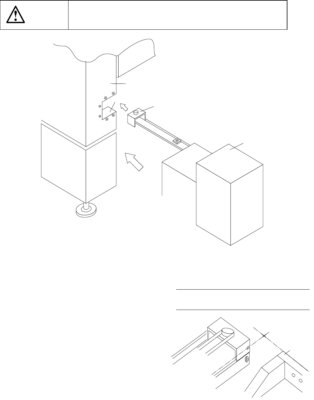
Figure 12.5.1
1) Move the MTC main unit 4 from the rear
so that the MTC shuttle section 3 can be
inserted under the MTC guide cover 1
which is located on the right far side with
viewed from the front of the main unit.
2) Slide the MTC main unit 4 toward the
cover RUR 2 as close as possible, then
install the MTC.
3) Adjust the adjuster foot of the MTC main
unit so that the shuttle tip cut-out can
be located at a height of the top side of
the fixing plate.
Figure 12.5.2 A arrow-view figure
① MTC guide cover
② Cover RUR
③ MTC shuttle section
④ MTC main unit
⑤ Front plate
①
②
③
④
←
←←
←A
REAR 79
Note: Refer to the supplied Instruction
Manual for how to operate an MTC.
12 − 7
4) Connect the MTC power plug ② and signal connector ③ to the corresponding
jack/connector and the air tube to the MTC air fitting of the interface panel located
on the right side of the main unit.
Note: Be sure to use the cable and air tube supplied with the MTC.
Figure 12.5.3
② MTC power jack
③ MTC interface connector
④ MTC φ 6 tube inlet
12 − 8
12.5.1 Installing the Matrix Tray Changer (MTC)
12.5.1.1 TR-4SN install start position
Figure 12.5.1.1 Appearance of TR-4SN to be installed
CAUTION
To avoid any accident caused by sudden activation of the machine,
turn off the power.