KE2010.Instruction Manual.Ver.2.01,Rev.08.pdf - 第739页
12 − 9 12.5.1.2 TR-6SN/TR-6DN install start posi tion Figure 12.5.1. 2 Appearance of TR-6SN/ TR-6DN to be installed CA UTION To avoid any accident caused by sudden activat ion of the machine, turn off the power.
12 − 8
12.5.1 Installing the Matrix Tray Changer (MTC)
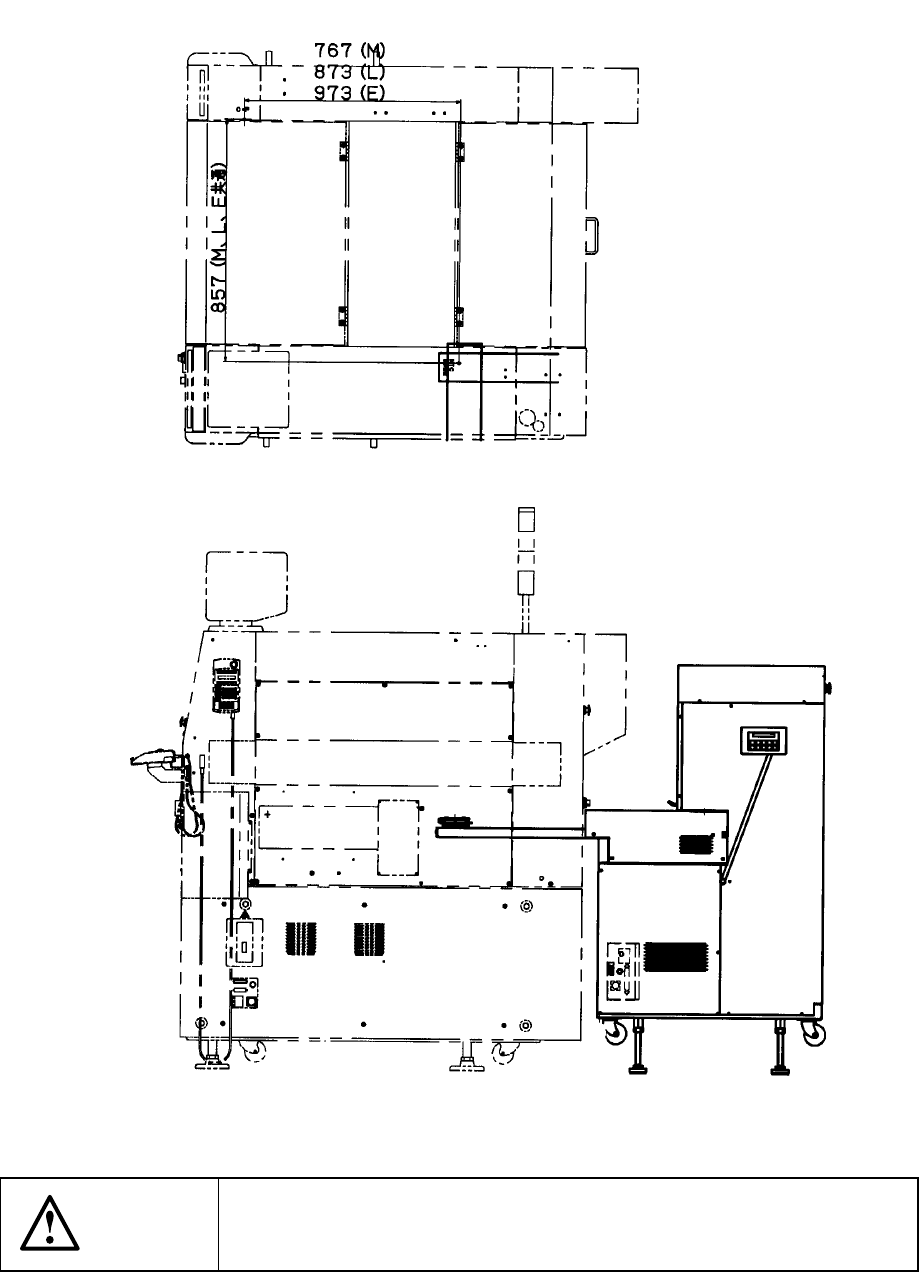
12.5.1.1 TR-4SN install start position
Figure 12.5.1.1 Appearance of TR-4SN to be installed
CAUTION
To avoid any accident caused by sudden activation of the machine,
turn off the power.
12 − 9
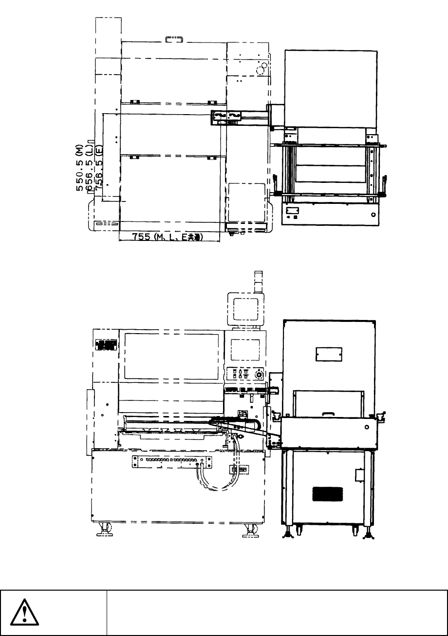
12.5.1.2 TR-6SN/TR-6DN install start position
Figure 12.5.1.2 Appearance of TR-6SN/TR-6DN to be installed
CAUTION
To avoid any accident caused by sudden activation of the machine,
turn off the power.
12 − 10
12.6 Handling the Feeder Position Indicator (FPI)
The FPI is located at the front of the number label (indicating the feeder mounting
position) for the feeder bank, and equipped with LEDs which correspond to the
number of each number label. These LEDs indicate the feeder mounting position or
component supply condition by lighting or flashing as follows:
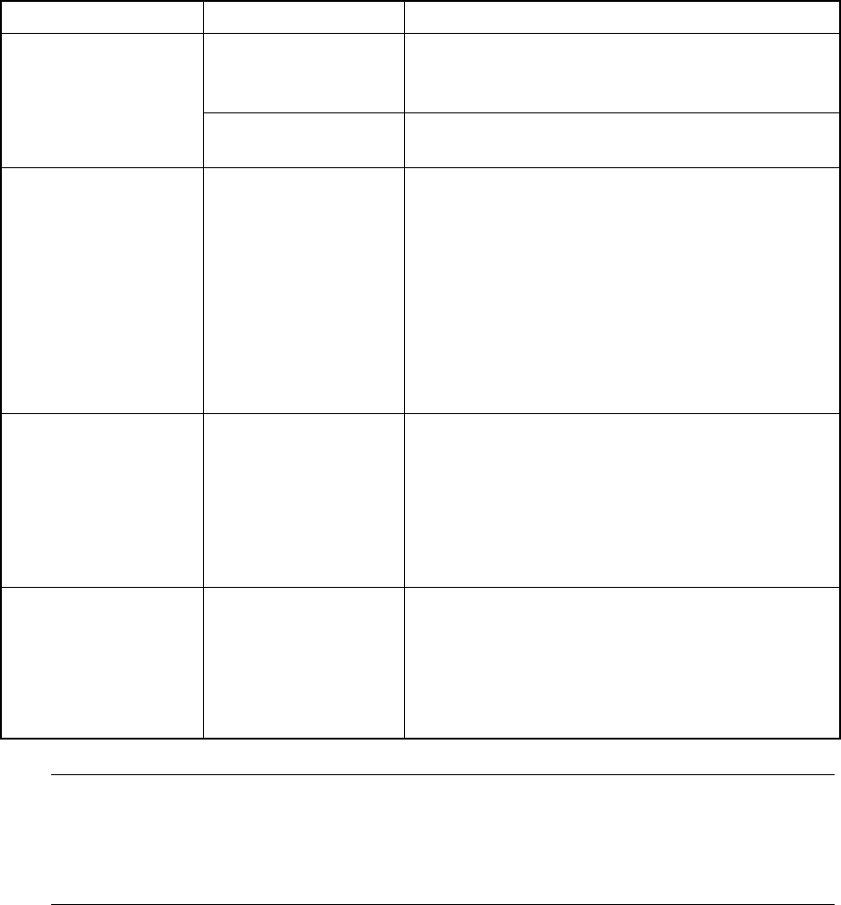
Table 12.6.1
Machine condition LED status Function
Flashing Indicates the hole (number) into which the
positioning pin is inserted to position the feeder
specified with the production program
Preparation
Lighting Indicates the range of the feeder bank which the
mounted feeder occupies.
Board production Flashing If the number of the components remaining at a
feeder gets less than the warning level which is
specified as the number of components in the
production program ( this value is set to notify an
operator that the number of the remaining
components is insufficient), the LED
corresponding to the position at which the feeder
is mounted flashes to indicate that the number of
the remaining components is not enough at the
feeder.
Components run-out Lighting If the number of the components remaining at a
feeder which is obtained based on the initial value
specified as the number of components in the
production program reaches "0" during production,
the LED corresponding to the position at which the
feeder is mounted lights to indicate that
components run out at the feeder.
Manually controlled When the feeder
knock pin is set to
ON: Lighting
OFF: Not light
If you use the feeder knock pin control function
which is provided on the Manual control menu to
feed tape or perform the direct knock action, the
LED located at each controlled feeder positioning
pin flashes according to the feeder knock pin
action to indicate which knock pin is controlled.
Note: Unless you enter the number of components to be fed to the feeder or
equivalent correctly at the menu item [Component no. setup] displayed on the
[Change] menu which is invoked from the menu command [Pwb Production],
the number of the remaining components is not displayed correctly and the
indication for component run-out is not displayed properly.