KE2010.Instruction Manual.Ver.2.01,Rev.08.pdf - 第74页
3 − 1 CHA PTER 3 OPERA TION OVERVIEW This chapter describes the operat ion overview of this machine: basic oper ation procedures and the sof tware config uration. 3.1 Operation Flow In this section, two types of operatio…
2 − 10
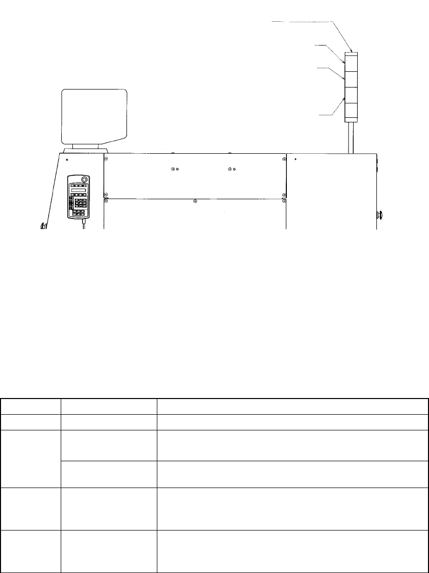
2.2 Rotary Beacon Tower (Signal Lights)
Figure 2.2.1 Upper right side of the main body
The following table lists the functions (factory-settings) of the three colored lamps of
the rotary beacon tower q. At the machine setup, however, these can be changed as
you desire (See Section 7.2.2.13 "Signal lights").
Table 2.2.1
Color Condition Function
Green Lit Production in progress
Lit • In Manual mode, program data is being created.
• The machine pauses during production.
Yellow
Flashing • Components running out during production (Production can
continue.)
Red Lit • Emergency stop or an error occurs.
• The machine cannot continue producing a board due to no
component available.
All lamps Lit • Waiting for the production START key to be pressed in
Production mode.
• Production completed normally, in Idle or other mode
Signal lights
Red
Yellow
Green
3 − 1
CHAPTER 3 OPERATION OVERVIEW
This chapter describes the operation overview of this machine: basic operation procedures
and the software configuration.
3.1 Operation Flow
In this section, two types of operation flows are described: when the machine is used
as a standalone machine and when several machines are used via the HLC.
3.1.1 When the machine is used as a standalone machine
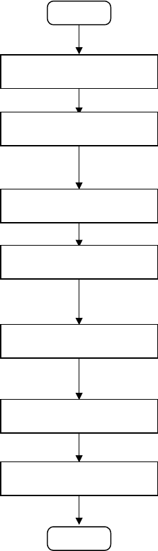
3.1.1.1 Producing new type of PWBs
The operation flow for producing new type of PWBs is shown below:
START
Editing a production
program
Preparation for production
Checking a production
program
Checking trial-run
operation
Continuous production
Post process
(2) Editing a production program
•
Create a production program.
(See Chapter 4 " EDITING THE PROGRAM ".)
You have to teach marks: BOC mark and IC mark. (See Section 5.4
"Teaching a Mark".)
(3) Preparation for production
•
At Set a feeder and check the nozzle assignment.
(See Chapter 6 "PRODUCTION PROCEDURES".)
(4) Checking a production program
•
Check to see if a production program is correct by tracking a component
placement position, pick-up position and pick-up height and measuring
them.
(See Chapter 4 " EDITING THE PROGRAM ".)
(5) Trial run
•
Perform the trial-run operation once or twice before starting continuous
production to check and adjust the results of components placement
operation
(See Chapter 6 "PRODUCTION PROCEDURES".)
(6) Continuous production
•
Produce the preset number of PWBs.
•
If the stocked components run out, supply components one by one.
(See Chapter 6 "PRODUCTION PROCEDURES".)
END
Setting the PWB
transport section
(1) Setting the PWB transport section
•
Set the PWB transport section according to a PWB to be produced.
(See Chapter 6 "PRODUCTION PROCEDURES".)
3 − 2
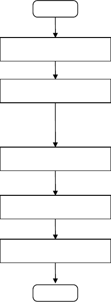
3.1.1.2 Repetitive production
The operation flow for producing PWBs repetitively is show below.
START
Loading a production
program
Preparations for production
(Changeover)
Checking trial-run operation
Continuous production
Post process
(1) Loading a production program
•
Load a production program which was already edited in order to
produce PWBs.
(See Chapter 3.6 " File Operation ".)
(2) Preparations for production (Changeover)
•
At the machine station, adjust the width of the PWB transport path,
position and adjust the reference pin or stopper pin, adjust the backup
support pin, check the nozzle assignment, and install a feeder.
•
After installing a component pick-up device, check and adjust the
component pick-up position.
(See Chapter 6 "PRODUCTION PROCEDURES".)
(3) Trial run
•
Before starting continuous production, perform the trial-run operation
once or twice to check and adjust the results of components
placement.
(See Chapter 6 "PRODUCTION PROCEDURES".)
(4) Continuous production
•
Produce the preset number of PWBs.
•
If the stocked components run out, supply components one by one.
(See Chapter 6 "PRODUCTION PROCEDURES".)
END