KE2010.Instruction Manual.Ver.2.01,Rev.08.pdf - 第742页
12 − 12 12.8 Handling HMS The HMS (Height Measurement System ) is an optional device used to detect the height of a component such as a feeder pick position. This optional device consists of two parts: the height sensor …
12 − 11
12.7 Handling Bad Mark Sensor
1) Color and size of a bad mark
a) A bad mark on a PC board to which green resist is applied shall be a glossy
white mark of 2.5 mm in diameter or greater.
b) A bad mark on a white ceramic PC board shall be a black mark of 2.5 mm in
diameter or greater.
c) The bad-mark reader cannot recognize the smaller or faded marks. The
bad marks shall be clear and legible.
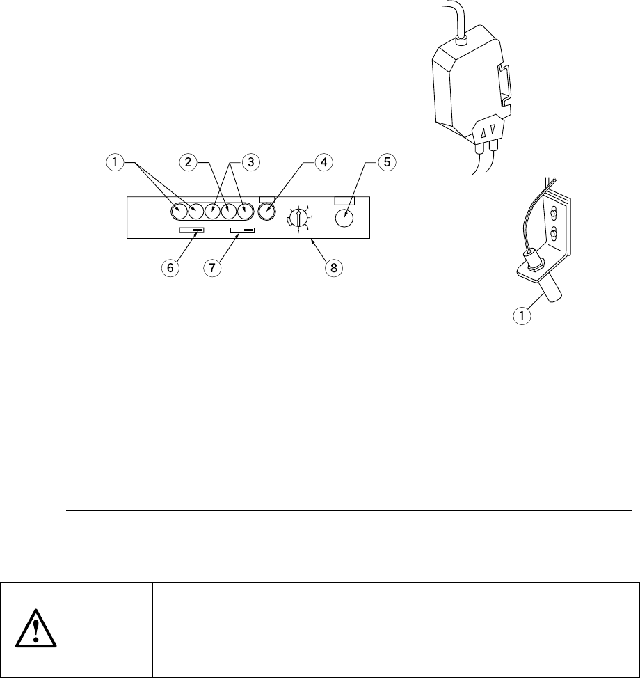
2) Figures 12.7.1 and 12.7.2 show the bad-mark sensor appearance. For details of
installation, see the explanation of the head section.
Figure 12.7.2 Figure 12.7.1
① Light receiving level indicator ⑤ SET button
② Input light indicator ⑥ Output timer switch
③ Spareness indicator ⑦ Output mode switch
④ SET indicator ⑧ Mode switch
3) Adjusting the sensitivity of the bad-mark sensor
Note 1: The software automatically adjusts the sensitivity of the bad mark sensor
(see Section 7.2.2.13 "Bad mark sensor teaching").
CAUTION
The sensitivity adjustment shall be performed only by the authorized
technician who received training for the operation of this machine.
Take care that any person other than the operator does not operate the
machine to prevent accidental activation of the machine.
12 − 12
12.8 Handling HMS
The HMS (Height Measurement System) is an optional device used to detect the
height of a component such as a feeder pick position.
This optional device consists of two parts: the height sensor which is composed of
the sensor and amplifier, and the HMS board which controls the height sensor. To
use this optional device, install it on the head unit.
The amplifier of the height sensor and the controls and switches located on the HMS
board are all already set at the factory. Do not change their settings.
Sensor part Amplifier part
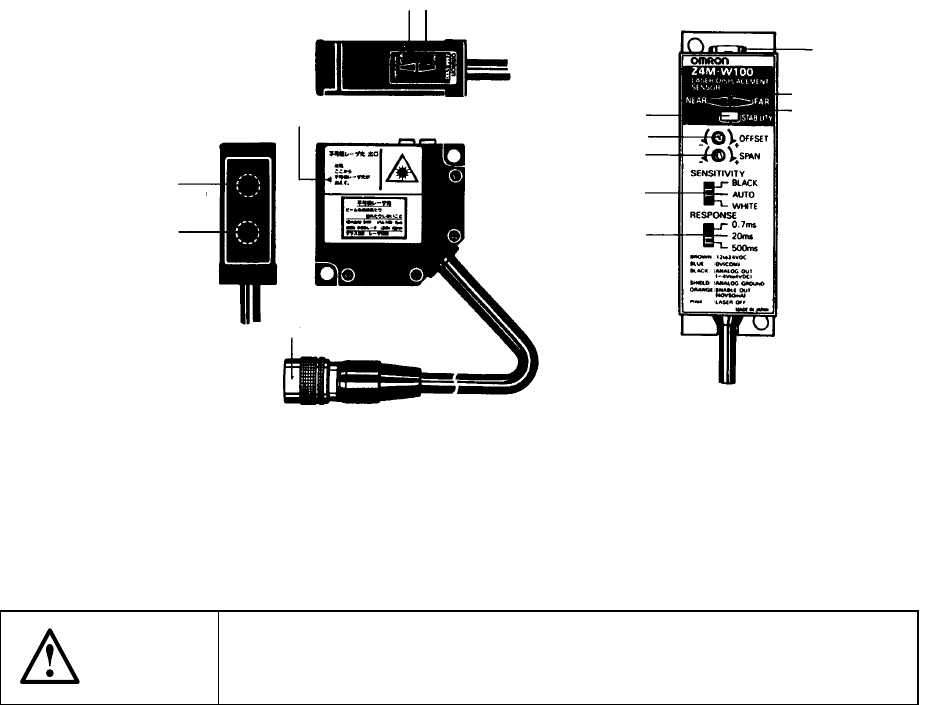
Figure 12.8.1
The HMS conforms to Class 3B Laser Safety Standard of JIS C6802.
It can be used safely when following the instructions described in this manual.
CAUTION
The laser beam used for the high sensor is invisible. Be careful not to
expose you to the beam or do not try to view the beam.
Photo-transmitting section
(laser emitting section)
Photo-receiving section
Connector
Laser emission mark
Ran
g
e indicator
(
NEAR indicator
)
(
FAR indicator
)
STABILITY indicato
r
OFFSET adjustment control
SPAN adjustment control
RESPONSE speed switch
SENSITIVITY switch
(NEAR indicator)
(FAR indicator)
Connector
Range indicator
12 − 13
12.9 Replacing Overall feeder exchange trolley
3
9
11
1
5
4
8
7
6
13
15
2
14
12
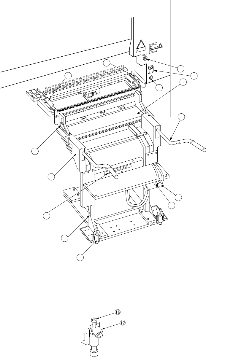
Figure 12.9.1 Overall feeder exchange trolley
Figure 12.9.2 Trolley stopper t
⑯ Lock pedal
⑰ Lock release pedal