KE2010.Instruction Manual.Ver.2.01,Rev.08.pdf - 第748页
12 − 19 12.12 Handling a Gripper Nozzle This nozzle is designed exclusively f or the KE- 2000 series of pr oducts to pick up and/or place on a board a com ponent whose top has no picked-up ar ea, and it is available to l…
12 − 18
12.11 Handling a Portable Type Tray Server (DTS)
If you attach or remove a DTS while the XY axis or head is operating,
the DTS may come in contact with a part that is moving, and you may
be injured or the machine may be damaged.
Do not attach or remove any DTS onto/from the machine while the XY
axis or head is operating.
After attaching the DTS onto the machine, secure the safety by
eliminating any clearance into which your hand or finger happens to be
put, for example by attaching an unused tape feeder on the clearance.
Procedure for attaching/removing a DTS
Refer to the Instruction Manual supplied with the DTS.
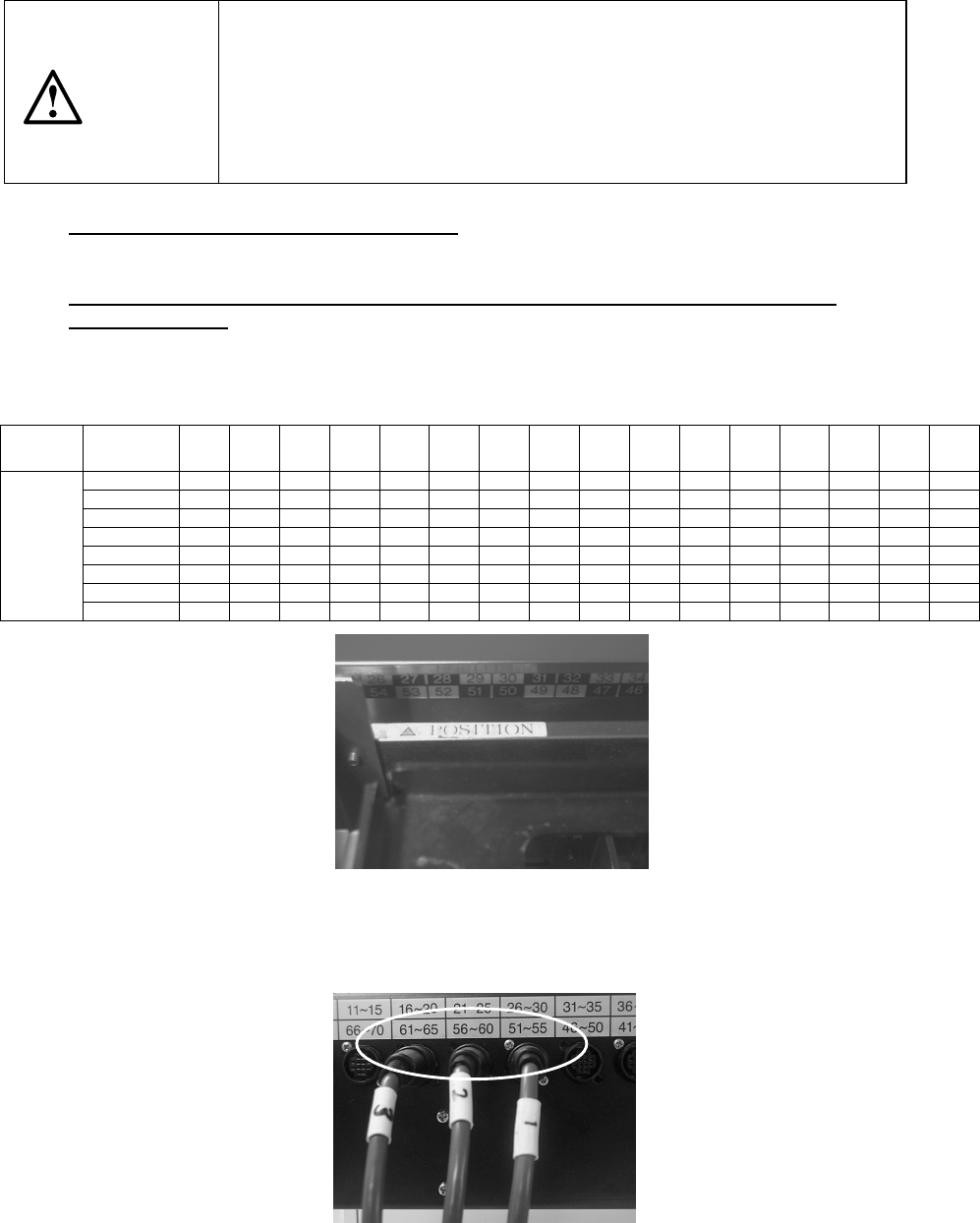
Attaching position (relation between the feeder bank number and the connector
bracket number)
The position of the DTS cable to be connected to the connector bracket may vary
depending on the feeder bank number the DTS is to use.
Table 12.11 DTS cable position
Feeder
bank
number
76~79 71~75 66~70 61~65 56~60 51~55 46~50 41~45 36~40 31~35 26~30 21~79 16~20 11~15 6~710 1~5
Rear 76 to 77 ① ② ③
Rear 71 to 75 ① ② ③
Rear 66 to 70
① ② ③
Rear 61 to 65
① ② ③
Rear 56 to 60 ① ② ③
Rear 51 to 55
① ② ③
Rear 46 to 50
① ② ③
Connector
bracket
number
Rear 45 ① ② ③
*
①
: DTS P1-3-pin connector
②: DTS P2-3-pin connector
③: DTS P3-3-pin connector
Figure 12.11.1 Example: When “
△
POSITION” is set to the number 53 (it is
assumed that this is set as the device enabled on the Setup menu).
The feeder bank numbers “51 to 55” are applied to this unit according to the table
above.
Figure 12.11.2 onnect the No.
①
connector to the connector bracket number “51
to 55”, No.
②
connector to “56 to 60” and No.
③
connector to “61 to 65.”
CAUTION
12 − 19
12.12 Handling a Gripper Nozzle
This nozzle is designed exclusively for the KE-2000 series of products to pick up
and/or place on a board a component whose top has no picked-up area, and it is
available to laser and vision recognition.
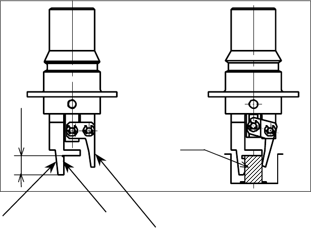
1. Features
The gripper nozzle uses its “fixed arm” and “swing arm” together exclusively to
pick up and/or place a component whose topside has no picked-up area. Its grip
strength is appropriate enough to pick up/place a component stably.
①
Fixed arm
②
Swing arm
Figure 12.12.1 Name of each part of a nozzle
①
①①
①
②
②②
②
Com
p
onent
Position against a
component is pushed
Len
g
th of a lu
g
12 − 20
2. Specifications
(1) Required components and software
− A floppy disk on which a nozzle information file is stored is supplied with a
nozzle. This disk is required to use a gripper nozzle.
− The software version of the main unit that supports control over a gripper
nozzle is 1.11 or higher.
− The dimensions of a gripper nozzle arm should match a shape and size of
each component and a shape of a feeder such as a tape and tray.
[See “(5) Applicable components and packaging style”.]
(2) Method
Centering method: Laser and vision
(3) Component placement precision
Component placement precision : ± 0.3 mm or less (3 )
Note that the attained precision may vary depending on the shape of a
component.
When the system places a component whose portion to be aligned with laser
has an edge, whose molded part has a burr, or whose portion to be inspected
with the system cannot be fixed to a pick-up device, the precision described
above cannot be attained.
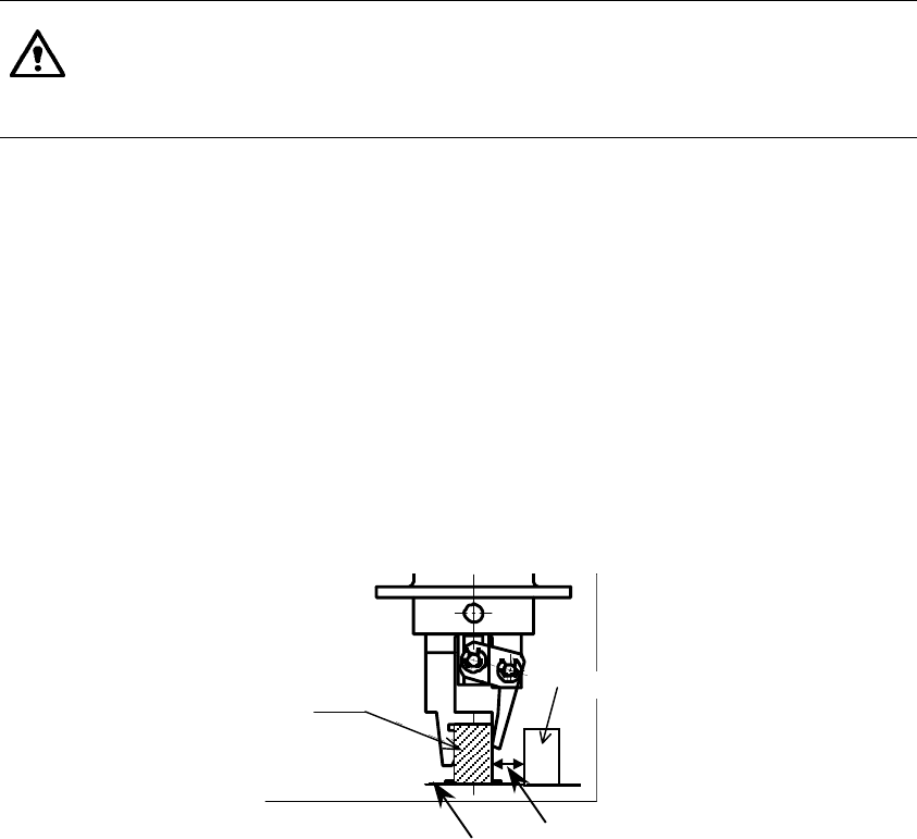
(4) Limited adjacent components
When the system places a component, a gripper swing arm opens, so it may
be in contact with an adjacent component.
Therefore, there are the following two restraints on operations of a gripper
nozzle:
− The height of a component to be placed with a gripper nozzle should be 3
mm or more higher than that of adjacent components.
− The side of a component to be held with the swing arm of the gripper
nozzle should be far from adjacent components by 4 mm or more.
(See the figure below.)
Component B
Component A
Board Note: Components A and B
should another by at
least 4mm.