KE2010.Instruction Manual.Ver.2.01,Rev.08.pdf - 第752页
12 − 23 ② Entering inf orm ation f or contr olling a component position picked up by a gripper nozzle Figure 12.12. 5 Setting the gri pper control infor mation Distance between the fix ed arm and the center of a componen…
12 − 22
3. How to Use a Gripper Nozzle
3.1 Load information on a gripper nozzle from a floppy disk on the Machine
Setup menu.
* Once you load information, it is stored on the machine, so you do not have
to perform this operation every time you use the machine.
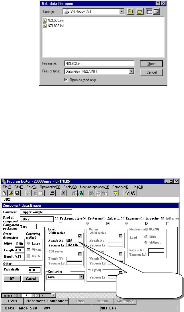
− Select the [Read nozzle data] command on the “File” menu invoked from
the Machine setup menu. The following “Nzl. data file open” dialog box
appears. Load the nozzle information file for a gripper nozzle from a
floppy disk.
(See the chapter on the Machine Setup menu for details.)
Figure 12.12.3 “Nzl. data file open” dialog box
3.2 Creating Component data
See the chapter on Component data for details on the operation to be
performed.
− Component data creating example
The following example shows how to create Component data that specifies
gripper nozzles to be used.
① Setting the nozzle number
Figure 12.12.4 Setting the nozzle number
The gripper nozzle
number is from 800
to 899.
12 − 23
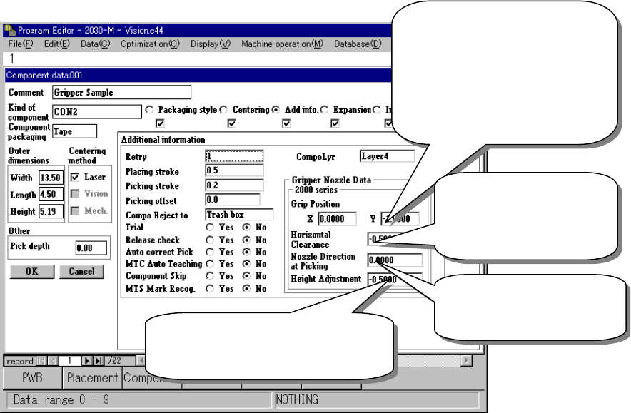
② Entering information for controlling a component position picked up by a
gripper nozzle
Figure 12.12.5 Setting the gripper control information
Distance between the fixed arm
and the center of a component
- Enter the width of the molded
part of a component (half) into
the “Y” field.
- Do not enter any value other
than “0” into the “X” field.
Clearance between the
fixed arm and the
component molded part
(Enter a negative value.)
Specify the angle of a
nozzle (Enter one of 0,
90, 180 and 270.
)
A griper nozzle has a dumper. To
hold a component horizontally, enter
about – 0.5 mm as a push-in stroke.
12 − 24
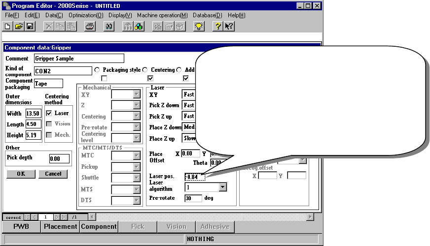
③ Laser pos. (position)
Be careful to enter this setting item when you use a gripper nozzle.
Normally, enter the distance from the top of a component to the surface on
which laser beam impinges in the “Laser pos.” field of a nozzle. However,
when you use a gripper nozzle, enter the distance laser is beamed by
regarding the tip of the nozzle that is located at the fixed arm as a reference
position.
Figure 12.12.6 Setting the laser height
Specify the distance from the tip of a nozzle to the
surface on which laser beam impinges.
Setting guide: - (component height – 3.5 mm) / 2
Make trivial adjustments of this
value according to a lead position.
Example shown on this screen: - (5.19 – 3.5) / 2
= - 0.84