KE2010.Instruction Manual.Ver.2.01,Rev.08.pdf - 第756页
12 − 27 3.4 Differences betw een a KE- 2000 series of product and a KE- 750/760 − The dif f erences on operat ions are shown below w hen you use a g ripper nozzle: Data ty pe Setting item KE-750/760 KE-2000 series Setup …
12 − 26
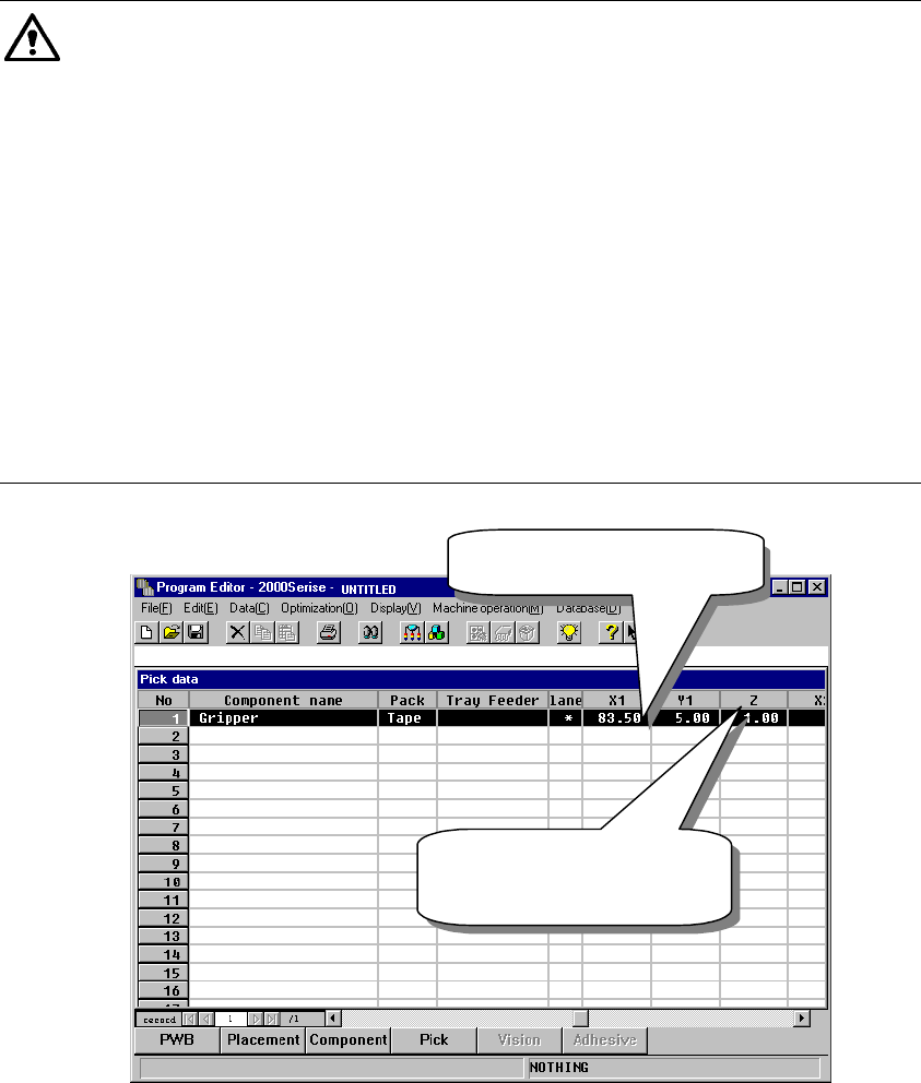
3.3 Pick Data
Pick data to be created when you use a gripper nozzle is the same as that for
a standard nozzle. Therefore, you do not have to perform teaching
operation for the gripper arm position and the height of the nozzle section
against which the component topside should be pushed.
① X and Y coordinates: the center of a component is used as the reference
position.
② Z coordinate: the tip of the nozzle (Height of an edge of the fixed arm =
Height of the normal nozzle) is used as a reference position.
Caution
Note that how to set data with a KE-750/760 is different from that with the
KE-2000 series of products when you use a gripper nozzle. To use a gripper
nozzle with a KE-750/760, you have to teach a component pick-up position.
Teaching operation is required for making fine adjustments of a component
pick-up position; set the Y coordinate far from the fixed arm by about 1 mm
by checking it with your eyes, and set the Z coordinate so that the middle
section of a gripper nozzle against which the top of a component is to be
pushed can be just in contact with the top of a component located on the
feeder. However, the KE-2000 series of products allow you to use a gripper
nozzle without teaching a component pick-up position. The system makes
fine adjustments of a component pick-up position according to the nozzle
information (loaded from a floppy disk) or allow you to set the position in
Component data if a component is very unique.
Figure 12.12.8 Setting Pick data
XY: Center of a
component
Z: set based on the tip of
a nozzle as the
reference position.
12 − 27
3.4 Differences between a KE-2000 series of product and a KE-750/760
− The differences on operations are shown below when you use a gripper
nozzle:
Data type Setting item KE-750/760 KE-2000 series
Setup data Gripper nozzle
setting
Select the [g/Gripper nozzle]
command on the Setup menu, and
specify a number from 130 to 149
on the opened dialog box.
Select the [Read Nzl. data]
command on the “File” menu to
load information on a gripper
nozzle from a floppy disk. Then
operate the system in the same
manner as you do for a normal
nozzle.
Nozzle number 130 − 149 800 − 899
Centering method Laser only Both laser and vision
Component height Height of a portion that is
protruded from the tip of a nozzle
Height of a component itself
Laser height - 0.3mm − - 0.5mm Basically set laser height in the
same manner as you enter it
with a KE-750/760.
Enter the distance between the
edge of the fixed arm and the
molded part on which laser
beam impinges.
Component
data
Nozzle data in the
“Additional
information”
No setting item in Component
data.
(You have to perform teaching
operation if there is no Pick data
on a KE-2000 series of product.)
Specify the setting items, “Grip
Position”, “Horizontal
Clearance”, “Nozzle Direction at
Picking” and “Height
Adjustment”, which are designed
to require no entry for teaching a
component pick-up position.
Pick data Y coordinate Teaching is necessary for the
fixed side arm to be located far
from a component by about 1 mm.
Center of a component
Z coordinate The center of a gripper nozzle is
regarded as a reference position
of the top of a component.
Teaching is necessary for this side
to be the top of a component.
The tip of a nozzle is regarded
as the reference position.
(The tip of a gripper nozzle is
located at the height of the tip of
a standard nozzle.)
The system can pick up a
component relatively stably
without teaching its pick-up
position.
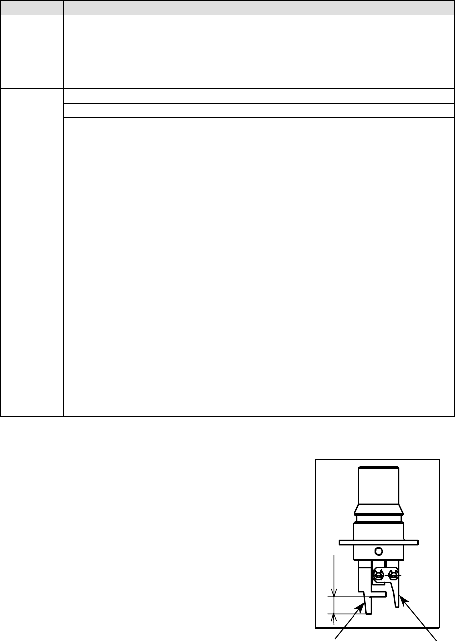
3.5 Direction a Gripper Nozzle Is Attached onto an ATC
View the ATC unit from its front, and
install a gripper nozzle onto the ATC
so that the fixed arm of the gripper
nozzle (1 in the figure below) can be
located on the rear, and the swing
arm (2 in the figure below) can be
located on the front.
①
①①
①
②
②②
②
Length of a lug
13 − 1
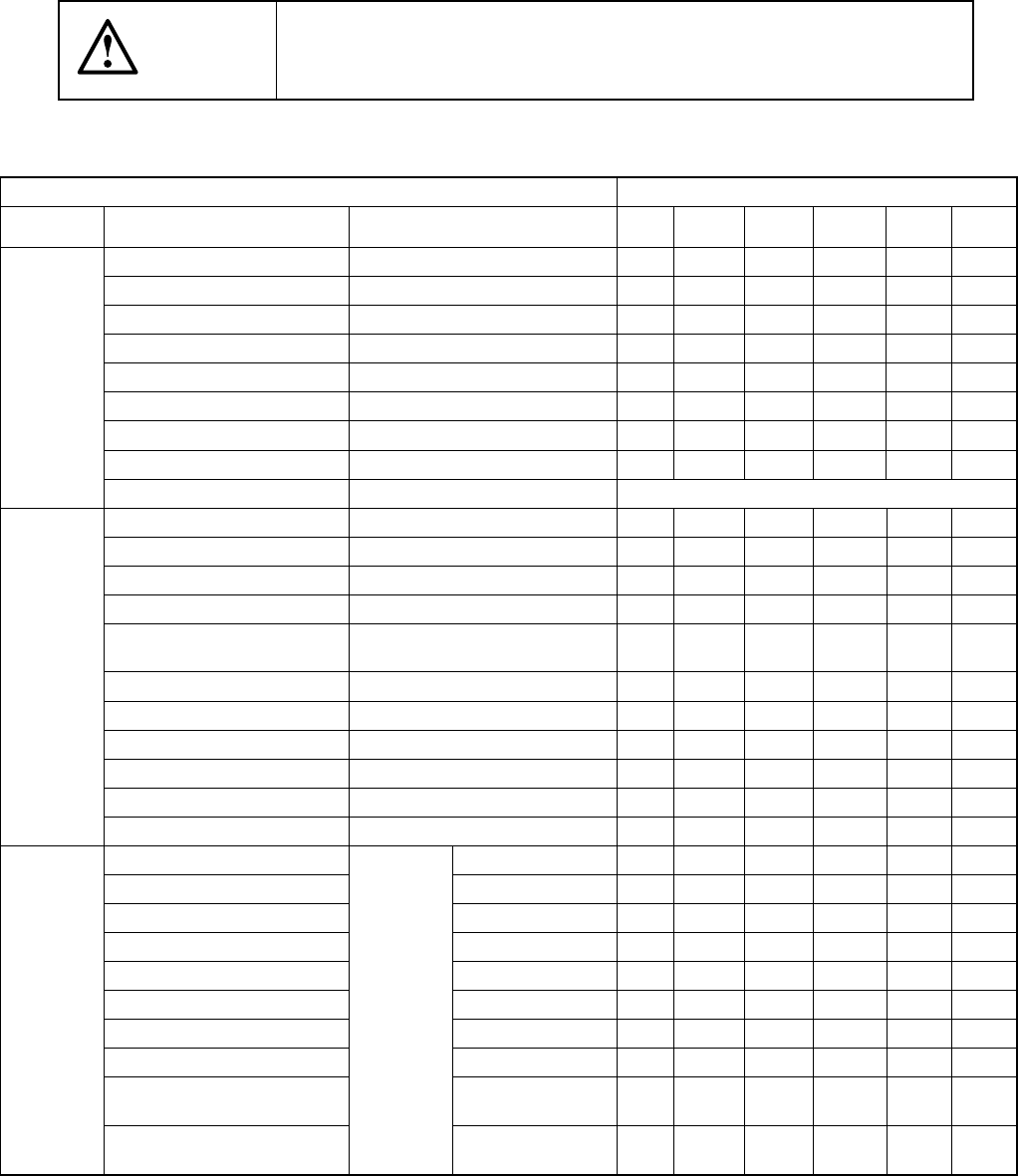
CHAPTER 13 MAINTENANCE
13.1 Daily Routine Checks
13.1.1 List of daily routine checks
WARNING
To prevent the body from injury which can be caused by accidental
activation of the machine, cut off the power to the machine before
starting to work.
Table 13.1.1
Items to be checked
Check and lubrication frequency
Maintenance
Check point
Check
Daily
Weekly
Monthly
Bimonthly
Every
half year
Every
year
Air pressure Check 0.49 MPa (5kgf/cm2).
○
Piping and joint Air leakage
○
Unit air cylinder Check operation.
○
Air filter (Head) No dirt
○
Air filter (CAL block)
○
Power on lamp Check if it is lit.
○
Transfer belt Worn out, damage, or stretch
○
Transfer pulley If it functions properly.
○
Check
Electric device Voltage, cables, and connectors Whenever necessary
X- and Y-axis direct drive units Remove dirt and oil.
○
Transfer belt Remove dirt and foreign substances
○
Transfer sensors Cleaning
○
Laser align sensor Cleaning of the sensor window
○
Nozzle
Disassemble and cleaning inside the
nozzle
○
ATC bracket Remove dirt and oil.
○
Feeder bank Remove foreign substances.
○
Ejector Remove dirt and foreign substances.
○
Z slide shaft Cleaning inside the shaft.
○
OCC (Polarizing filter) Remove dirt and foreign substances.
○
Cleaning
Track ball Remove dirt and foreign substances.
○
X- and Y-axis direct drive unit rails Grease (EP2)
○
Transfer screw shaft (Shaft)
Grease (EP2)
○
Transfer guide shaft Grease (EP2)
○
PWB stopper part Grease (EP2)
○
Ball screw and LM guide rail (Head part)
Grease (CGrease)
○
Spline shaft (head part) Grease (CGrease)
○
Overall feeder exchange trolley Grease (EP2)
○
Support table Grease (EP2)
○
Movable transfer table section
(ball screw)
Grease (CGrease)
○
Lubrication
Movable transfer table section
(LM guide)
Smooth
movement
Grease (CGrease)
○