1OM-1603-006_w.pdf - 第142页
1OM-1603 3-17 2. Pattern Program Change : Chap.3 1012-001 (6) Connect the connector of the cart to the connector on the machine side and set the connector xing lever in place. Notice When the bank feeder change cart mus…
1OM-1603
3-16
2. Pattern Program Change : Chap.3
1012-001
2.2.5 Replacement of Bank Feeder Change Cart
CAUTION
Do not put your hand in the moving area while the
feeder base is moving up or down.
While the LED of the Feeder Ready switches are being
ickering, it indicates that the corresponding feeder base
is moving up and down.
Procedure
(1) Press the Feeder Ready switches of the machine.
(The feeder READY switch LED will be extinguishes and the feeder base is
unclamped.)
(2) Keep pressing the Feeder Ready switches of the machine a little longer.
(The feeder base starts moving down and the LED of the Feeder Ready
switches starts ickering, indicating that the feeder base is being activated.)
When the disconnection operation of the bank feeder change cart is
completed, the LED of the Feeder Ready switches extinguishes.
(3) Detach the connector xing lever and pull out the connector for the bank
feeder change cart from the connector to the machine. Then, catch the
connector on the magic tape section on the side of the cart.
Notice
(a) Do not use the connector catching section for any purpose
otherthanforcatchingthespeciedsectionoftheconnector.
Also, do not put any excessive force on it. Doing so might
damage the connector.
(b) During the machine operation, do not disconnect the connector.
For the feeder base connector, connect or disconnect it when
the feeder base is lowered to the end and it has stopped.
(4) Release the two stopper brakes of the bank feeder change cart and draw out
the cart from the machine.
(5) Insert the bank feeder change cart (provided with the tape feeders set ready
for use) into the machine and lock the two stopper brakes.
Notice
(a) When the bank feeder change cart must be pushed into the
machine, push it straight such that the guide on the machine
side can be located inside the cart arm.
Also, insert it taking care that your hand holding the cart handle
does not hit the cover.
(b) When the cart is not positioned correctly, the connection
operation cannot be performed.
Besuretopushthecartrmlyuntilittouchesthestopper.

1OM-1603
3-17
2. Pattern Program Change : Chap.3
1012-001
(6) Connect the connector of the cart to the connector on the machine side and
set the connector xing lever in place.
Notice
When the bank feeder change cart must be pushed into the
machine, push it straight such that the guide on the machine side
can be located inside the cart arm.
(7) Press the Feeder Ready switches of the machine.
(The feeder base starts moving up and the LED of the Feeder Ready switches
starts ickering, indicating that the feeder base is being activated.)
(8) Press the Feeder Ready switches of the machine.
The feeder READY switch LED is turned ON and the feeder base is
clamped.
1OM-1603
3-18
2. Pattern Program Change : Chap.3
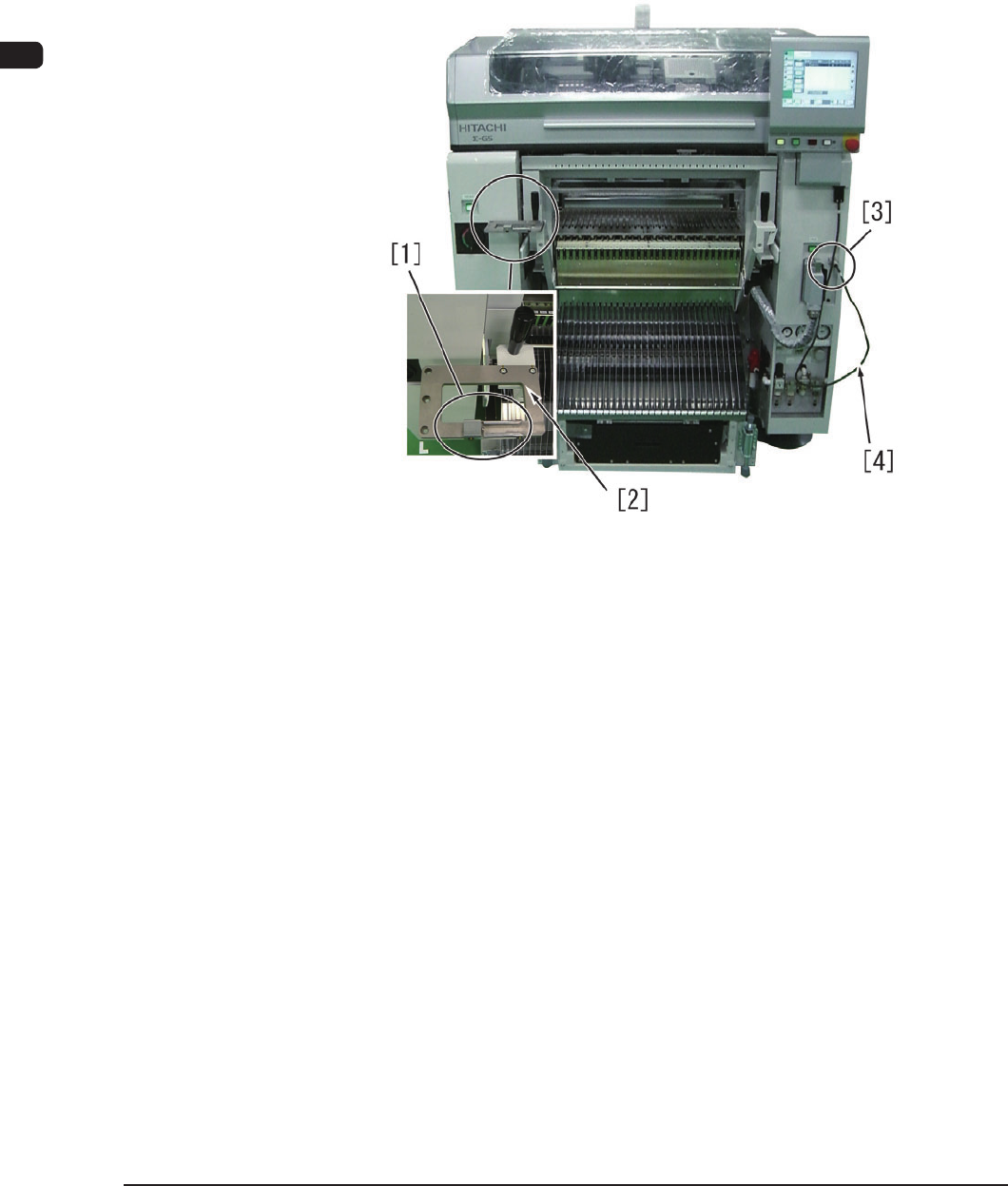
2.2.6 How to Use the Feeder Set Jig
The feeder set jig is a table for the tape feeder to x it temporarily when the
component reload work is performed for the tape feeder where the splicing
operation is not to be performed. Also, the power can be supplied from the main
machine using the tape feeder setting connector and a cable. This jig enables the
operator to perform the component reload work or adjustment work for each tape
feeder.
F1C13-1
[1] Tape Feeder Holding Guide
This guide holds the tape feeder when a single tape feeder is adjusted.
[2] Tape Feeder Fixing Base
This base is used to put the tape feeder on it.
[3] Tape Feeder Power Connector Socket
This connector is used for tape feeder DC power output.
[4] Tape Feeder Connecting Cable
Using this cable, the tape feeder power connector is connected to the tape
feeder connector to supply the power to the tape feeder.
1108-001