1OM-1603-006_w.pdf - 第192页
1OM-1603 4-5 1.Specications:Chap.4 1007-004 It em Descriptio n 10. Conditions of PCB before Placement (Regulation of Co m ponent Height) Un it : mm F1E8 Notes : (a) The po s ition of the P CB s upport pin can be m ov…
1OM-1603
4-4
1.Specications:Chap.4
1007-004
Item
Description
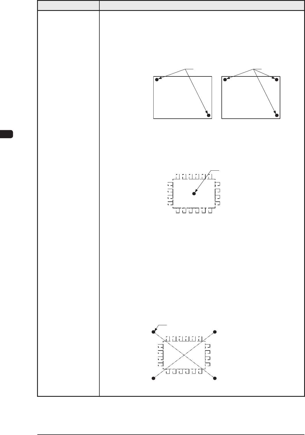
Example :
To correct the positional deviation covering the whole area of PCB (PCB
Overall Correction)
To improve recognition accuracy, put fiducial marks diagonally on two
places of PCB when the 2-point recognition mode is selected. In the case of
3-point recognition mode, put two fiducial marks diagonally and one
fiducial mark close to one of the remaining corners.
PCB
Fiducial Mark
PCB
Fiducial Mark
F1E5
Example 1 : To correct the positional deviation of component placement
points (1-point recognition)
Put a fiducial mark on the center of component placement point
or a desired point around the center.
Recommended Position: Center of Component Placement Point
Fiducial Mark
F1E6
Example 2 : To correct the component placement point
(2-point recognition)
Put fiducial marks on the desired two points around the center
of component placement point.
Recommended Position : Point Symmetry
It is recommended that two points (fiducial marks)
should be located symmetrically on both sides of
the center of the placement position.
(A-A'/B-B')
• These fiducial marks are used to correct the component position and the
theta (angle).
The 2-point recognition is effective to correct deviated and distorted part
of the printing patterns.
Fiducial Mark
A
A'B
B'
F1E7
T1E1-4
1OM-1603
4-5
1.Specications:Chap.4
1007-004
Item
Description
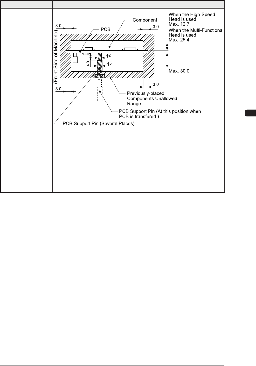
10. Conditions of
PCB before
Placement
(Regulation of
Component
Height)
Unit : mm
F1E8
Notes : (a) The position of the PCB support pin can be moved "10mm"
pitch by "10mm" pitch.
(b) The PCB support pin is set onto the position where it does not
touch any already placed component.
(c) The figure shows that the PCB is being supported.
(d) The dimensions are those for design reference.
Leave some room for the actual setting.
T1E1-5
1OM-1603
4-6
1.Specications:Chap.4
1007-004
Item
Description
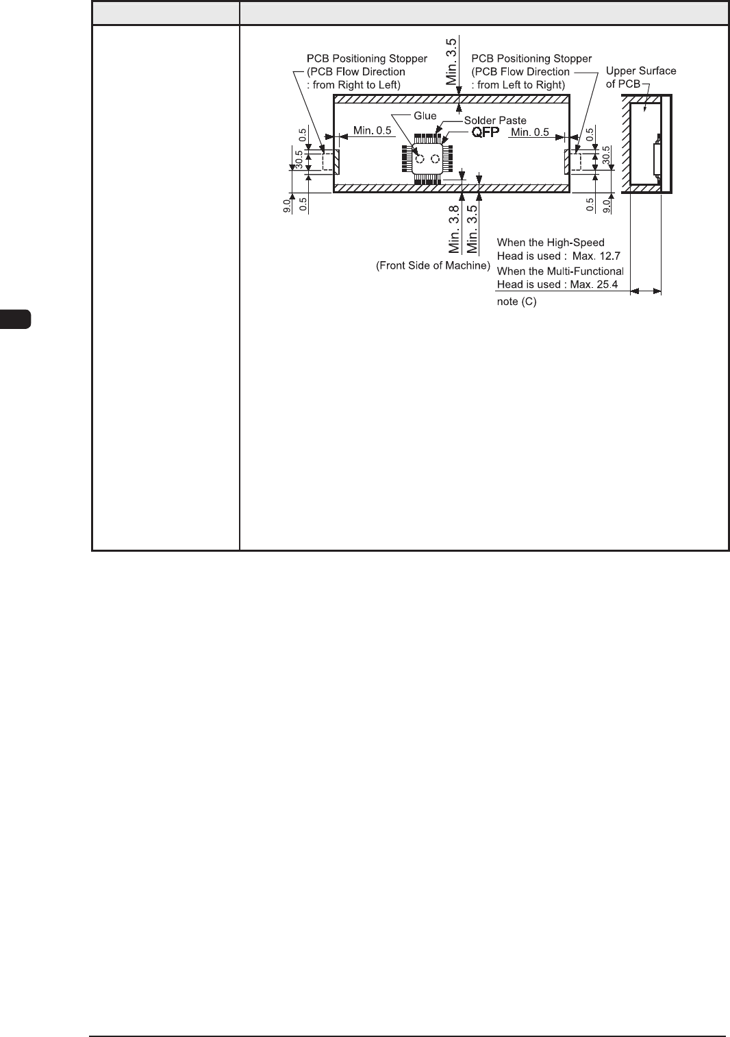
11. Component
Placeable Range
Unit : mm
F1E9
Notes : (a) The above figure shows that the vacuum nozzles are not
protruding from the outer shapes of components.
(b) Components cannot be placed in the shadowed area.
Components cannot be placed in the range (0.5 mm) around the
opening such as a hole.
(c) This size is the max. possible placement height including the
placed component height from the PCB.
T1E1-6