1OM-1603-006_w.pdf - 第198页
1OM-1603 4-1 1 1.Specications:Chap.4 1012-005 It em Descriptio n 16. Memory Capacity of Pattern Program Data Maximum Number of Steps : 20,000 s te ps/mod el (For rep etiti v e p atte rns) Maximum Memorized Number of …

1OM-1603
4-10
1.Specications:Chap.4
1012-005
Item
Description
High-Speed Head Multi-Functional Head 14. Number of
Stocked Nozzles
Nozzle Stocker for High-Speed
Nozzle
Max. 15 nozzles can be stored for
each stocker.
Nozzle Stocker for Middle-Size
and Odd Shaped Nozzle
Max. 8 nozzles can be stored for each
stocker.
Notes : (a) Increase of the quantity
of nozzle to be stocked
is available by means of
adding the nozzle
stockers (option).
(b) When the middle-size
odd shaped nozzle are
used, the nozzle stockers
for the middle-size odd
shape nozzle are
required.
Nozzle Stocker for Multi-
Functional Nozzle
Max. 9 nozzles can be stored for
each stocker.
Notes : (a) Use the nozzle stocker
for multi-functional
nozzle.
(b) Increase of the quantity
of nozzle to be stocked
is available by means of
adding the nozzle
stockers (option).
15. Number of
Installable Feeders
(1) Tape Feeders
Max. 60 feeders (30 tape feeders × 2 feeder bases)
(when only 8 mm dual tape feeders are used)
Ref. : Up to 120 types of components can be loaded.
Max. 60 feeders (30 × 2 feeder bases)
(When only 12 / 16 mm tape feeders are used)
Max. 30 feeders (15 × 2 feeder bases)
(When only 24 / 32 mm tape feeders are used)
Max. 20 feeders (10 × 2 feeder bases)
(When only 44 / 56 mm tape feeders are used)
Max. 14 feeders ( 7 × 2 feeder bases)
(When only 72 mm tape feeders are used)
(2) Vibratory Stick Feeders
Max. 5 feeders / feeder base
Ref. : Up to 6 carrier sticks can be installed on one vibratory stick feeder.
Notes : (a) The number of installable feeders varies according to the
combination of the reel width for the taping and the feeders.
(b) Use the tape feeder for the SIGMA-G4/G5. In the case that the
tape feeder for the GXH series is used, the operational conditions
are partly restricted.
(c) The tape feeder, dual tape feeder and bulk feeder for the other
machines cannot be used.
T1E1-10
1OM-1603
4-11
1.Specications:Chap.4
1012-005
Item
Description
16. Memory Capacity
of Pattern
Program Data
Maximum Number of Steps : 20,000 steps/model (For repetitive patterns)
Maximum Memorized Number of Models : 24 models
Note : The above numbers are limited according to the capacity of the
pattern program data per model.
17. Input System and
Output System of
Pattern Program
Data
• Operated using the touch screen on the main machine and edited using the
keyboard/pointing device (Option).
• Pattern program data can be edited with the network terminal (Option).
• Data can be entered through the local area network (Ethernet) running from
the data storage device of the network terminal (Option).
• Data Transfer to Storage of Network Terminal (Option).
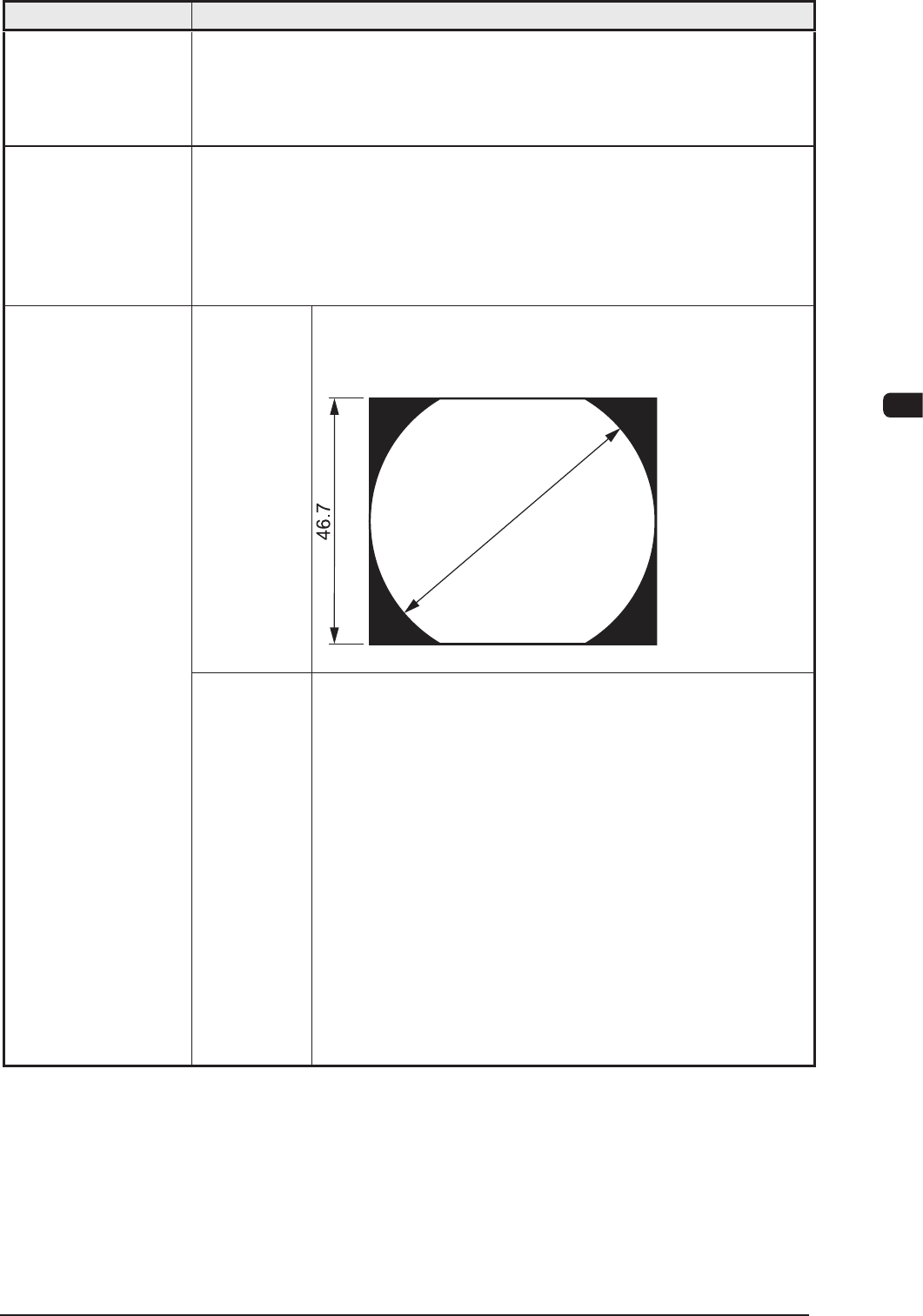
Visual Field φ 62 mm
The dimension in Y direction must be 46.7 mm.
Unit : mm
F1E10
18. Component
Recognition
Y (direction)
ø 62
Photo Image Front Lighting System
(Direct Recognition of Component by Front Lighting)
Note : Some limitation is imposed, depending on the types
of components.
Back Lighting System
(Recognition by Component Silhouette)
Note : Some limitation is imposed, depending on the types
of components.
In the back lighting system, specified nozzle are
required for the middle-size odd shaped nozzle and
the multi-functional nozzle on the multi-functional
head.
For the Back Lighting System, the static image is
shot using the camera.
T1E1-11
1OM-1603
4-12
1.Specications:Chap.4
1012-005
Item
Description
Visual Field Approx. 12 × 12 mm
Window
Size
Max. 9.0 × 9.0 mm
Recognition
(Process)
Time
Approx. 0.06 seconds / mark
(including the time to capture an image)
19. PEC Recognition
Photo Image Front Lighting System
(Recognition of Fiducial Mark by Front Lighting)
("Normal" or "Reverse" can be selected for each mark.)
20. Fiducial Marks Refer to "Fiducial Marks" for details.
Supply
Pressure
0.45 to 0.69 MPa (4.6 to 7 kgf/cm
2
)
Set Pressure 0.45 MPa (4.6 kgf/cm
2
)
Note : Min. 0.4 MPa (4.1 kgf/cm
2
) of air is necessary for
operation.
21. Air Supply
• Use the dry and clean air as follows
Moisture : Dew Point − 17 ℃ or lower (Atmospheric Pressure)
Oil : 0.1 mg/m
3
or less (ANR)
Dust : Solid Material 0.01 µm or less
22. Air Consumption Approx. 30 L/min (during automatic operation)
Approx. 110 L/min (when one feeder base moves up and down)
Approx. 220 L/min (when two feeder bases move up and down at the same
time)
23. Vacuum Pressure −93 kPa (70 cmHg)
24. Environmental
Condition
Temperature : 20
±
10
°
C
Humidity : 30 to 80 % (Avoid dew condensation)
Note : When the ambient temperature rises more than the surface of the
machine, dew condensation might occur under the condition described
below.
Note that dew condensation may cause the machine to break down.
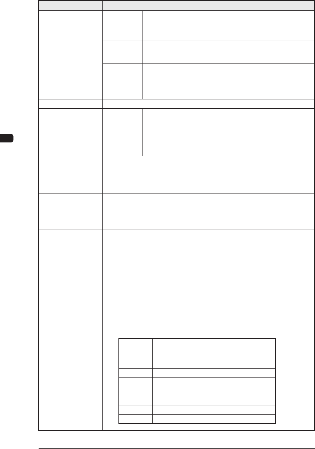
Condition of Dew Condensation
Dew condensation might occur when the difference (based on
"Humidity (%)") between the ambient and surface temperatures of the
machine reach the values or more in the table below.
Humidity
(%)
Differences between Ambient and Surface
Temperatures of Machine (Ambient
Temperature > Surface Temperature)
80 3 °C or more
70 6 °C or more
60 8 °C or more
50 10 °C or more
40 14 °C or more
30 18 °C or more
Altitude : 1,000 m or less above the sea level
T1E1-12