1OM-1603-006_w.pdf - 第205页
1OM-1603 4-18 3. Conditions for Component Placement : Chap.4 (3) Limit of Closest Distance to Obstacle • The closest distance between an obstacle (See each sectional view.) and the vacuum nozzle or component should be 0…
1OM-1603
4-17
3. Conditions for Component Placement : Chap.4
3. Conditions for Component Placement
(1)
When components are to be placed close to the previously-placed
components or the obstacles, the shape of the vacuum nozzle becomes part
of the constraint condition. Refer to "List of Nozzle Types" for the shapes of
vacuum nozzles.
(2)
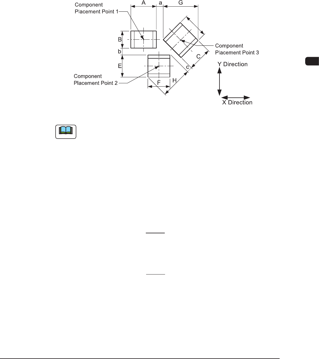
Adjoining Distances between Components
(when the component placement position is taken into consideration)
F1E11
Note
(a) F1E11 shows that the vacuum nozzles are not protruding from the
outer shapes of components.
When components are placed, any placement deviation may be
caused by solder paste, glue, etc. Here, we don’t take account of
such deviation.
(b) A to H in the above gure show the maximum dimensions including
the variations in the dimensions of each component. The minimum
adjoining distances (a, b, and c) of each component should be 0.2
mm.
(c) The minimum adjoining placement position data for component
placement points 1 and 3 is
X Direction Data = + Min. 0.2 mm
(The Y direction data is not related.)
(d) The minimum adjoining placement position data for component
placement points 1 and 2 is
Y Direction Data =
+ Min. 0.2 mm
(The X direction data is not related.)
(e) See F1E11 and obtain the minimum adjoining placement position
data for component placement points 2 and 3.
A + G
2
B + E
2
1012-005
1OM-1603
4-18
3. Conditions for Component Placement : Chap.4
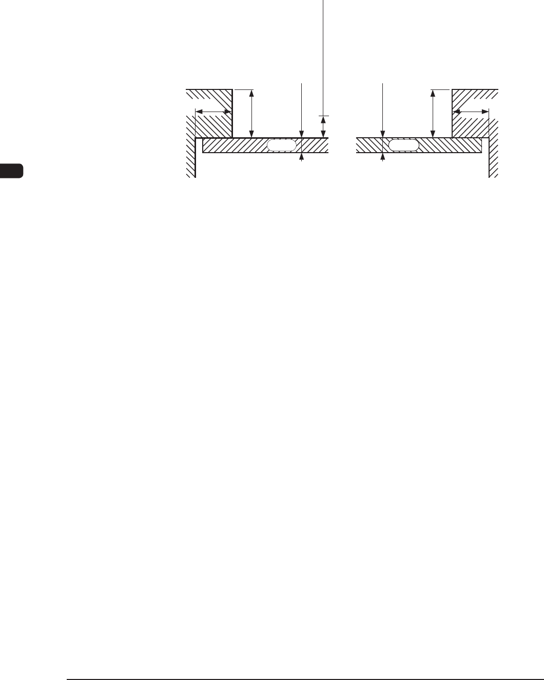
(3) Limit of Closest Distance to Obstacle
•
The closest distance between an obstacle (See each sectional view.) and
the vacuum nozzle or component should be 0.5 mm or more.
The upper surface of the PCB is the reference plane.
0.5 ot 3.0
0.5 ot 3.0
3.0
0.2
3.0
0.2
erom ro mm 5.0
PCB PCB
(Rear Side Machine)(Front Side Machine)
ecnatsiD tsesolC fo timiL
Unit : mm
Section View of Chute F1E12
1108-005
1OM-1603
4-19
4. Fiducial Marks : Chap.4
4. Fiducial Marks
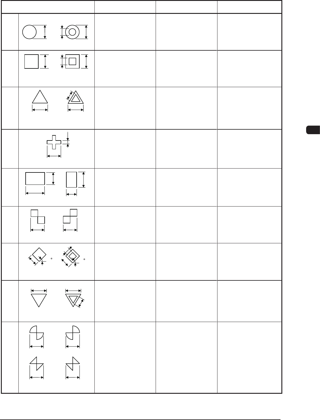
(1) Type and Size
Mark Type D1 [mm] D2 [mm] Remarks
dnuoR
0.3 to 3.0 0 to 2.8
(D1 - 0.2 = > D2)
• Mark Reference :
Center
• D2 :
Size of a punched
hole
erauqS
0.3 to 3.0 0 to 2.8
(D1 - 0.2 = > D2)
• Mark Reference :
Center of Gravity
• D2 :
Size of a punched
hole
laretaliuqE
elgnairT
)denrutpU(
0.5 to 3.0 0 to 2.8
(D1 - 0.2 = > D2)
• Mark Reference :
Center of Gravity
• D2 :
Size of a punched
hole
ssorC
0.5 to 3.0 0.2 to 1.5
(D1/2 = > D2)
• Mark Reference :
Center of Gravity
elgnatceR
0.5 to 3.0 0.5 to 3.0
• Mark Reference :
Center of Gravity
rekcehC
)erauqS(
0.5 to 3.0
−
•
Mark Reference :
Contact of Two
Squares
dnomaiD
)erauqS detatoR(
0.5 to 3.0 0 to 2.8
(D1 - 0.2 = > D2)
• Mark Reference :
Center of Gravity
• D2 :
Size of a punched
hole
laretaliuqE
elgnairT
)denrutnwoD(
0.5 to 3.0 0 to 2.8
(D1 - 0.2 = > D2)
• Mark Reference :
Center of Gravity
• D2 :
Size of a punched
hole
eiT woB
0.5 to 3.0
−
•
Mark Reference :
Contact of Two
Fan Shapes or
Triangles
2D
1D
1D
1D
2D
1D
(Front Side of Machine)
2D
D1
(Front Side of Machine)
(Front Side of Machine)
D1
2D
2D
D1
(Front Side of Machine)
D1
D1
D1
D2
D1
(Front Side of Machine)
Or
D1
D1
D1
Or
D1
(Front Side of Machine)
(Front Side of Machine)
D2
D1
D1
D1
45°
D2
D1
(Front Side of Machine)
45°
T1E4-1
1012-005