1OM-1603-006_w.pdf - 第66页
1OM-1603 1-9 2. Name and Function of Each Section : Chap.1 2.2.2.2 Cover Lock Switches The cover lock switches are used to permit the automatic operation of the selected stage section. Each stage is provided with a cover…
1OM-1603
1-8
2. Name and Function of Each Section : Chap.1
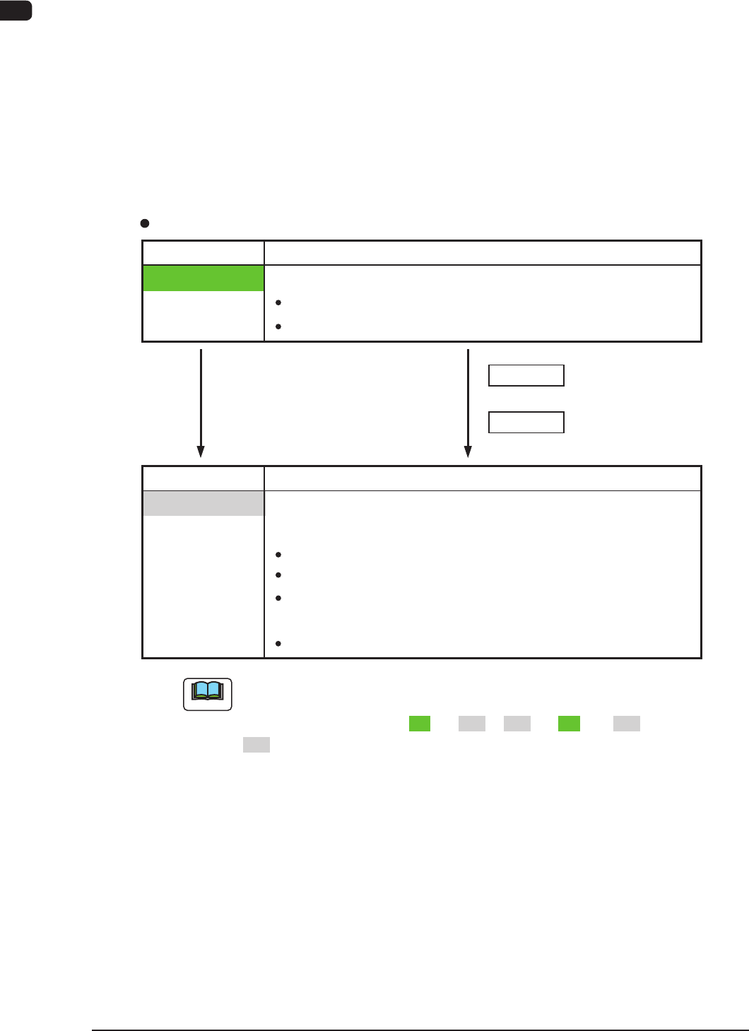
2.2.2.1 Feeder Ready Switches
The feeder ready switches are used to indicate that the feeder bases are set ready
and each switch is employed in each feeder block.
When the [START] button is pressed, the feeder clamp is activated and when the
machine is stopped or paused, the feeder clamp is released.
Also, this function enables the operator to perform operations while checking the
feeder pickup sections.
LED ON
Switch ON (Short Push )
LED OFF
S witch Operations and Tr ansition of Machine Condition
[Ordinary Operations with Machine in "STOP" (or "PAUSE") Mode]
Feeder Ready Switches
Switch Status Machine Status
Power Supply ( 24 V) to Feeders :
Switch Status Machine Status
LED OFF
" Replacement and Setup Operations of Feeder Bank
Carriage Cart" Possible
Power Supply ( 24
V) to Feeders :
Intercepted
F eeder
Attachment/Detachment Operation :
Possible
Power Supply to Connector for
feeder Base Installed on Main Machine
:
Intercepted
Not e
D uring the transition of the machine status along with the above-described
switch operations, the FEEDER READY switches flicker, regardless of a
LED lighting pattern such as "ON" to "OFF", "OFF" to "ON", or "OFF" to
"OFF".
+
+
Switch ON (Short Push)
Powere d
:
Unlocke d Feeder Base Drop Prevention
F eeder
Attachment/Detachment Operation :
Impossible
LED OFF
" Operation of Feeder Ready" Permitted by Operator
1108-006
1OM-1603
1-9
2. Name and Function of Each Section : Chap.1
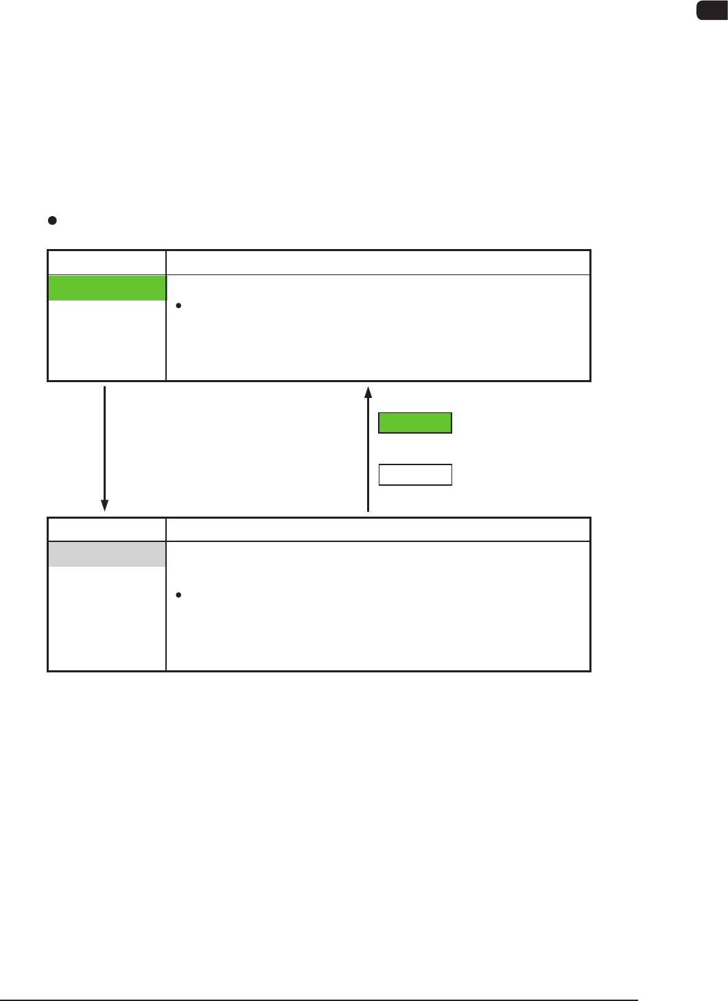
2.2.2.2 Cover Lock Switches
The cover lock switches are used to permit the automatic operation of the selected
stage section. Each stage is provided with a cover lock switches.
While the LED of the switch is ON, the transparent cover (door type) on the
selected stage cannot be opened because it is locked electromagnetically.
The LED cannot be turned on with the transparent cover kept open.
In addition, no power is supplied to the main circuit of the beam when the LED of
the "Cover Lock Switches" are turned ON.
The main circuit is powered only when the LEDs of both related stage and
"Feeder Ready Switches" are turned ON.
Switch ON
LED ON
Switch ON
LED OFF
Cover Lock Switches
Switch Status Machine Status
LED ON
"Cover Locking Operation" Permitted by Operator
Electromagnetic Locks of
Transparent Covers
(Door Type)
:
Locked
(Transparent Cover Opening
Impossible)
Switch Status Machine Status
LED OFF
"Cover Locking Operation" Rejected by Operator
Interception of Main Circuit for Pertinent Beam
Electromagnetic Locks of
Transparent Covers :
Unlocked
(Transparent Cover Opening
/ Closing Possible)
1108-006
1OM-1603
1-10
2. Name and Function of Each Section : Chap.1
1012-005
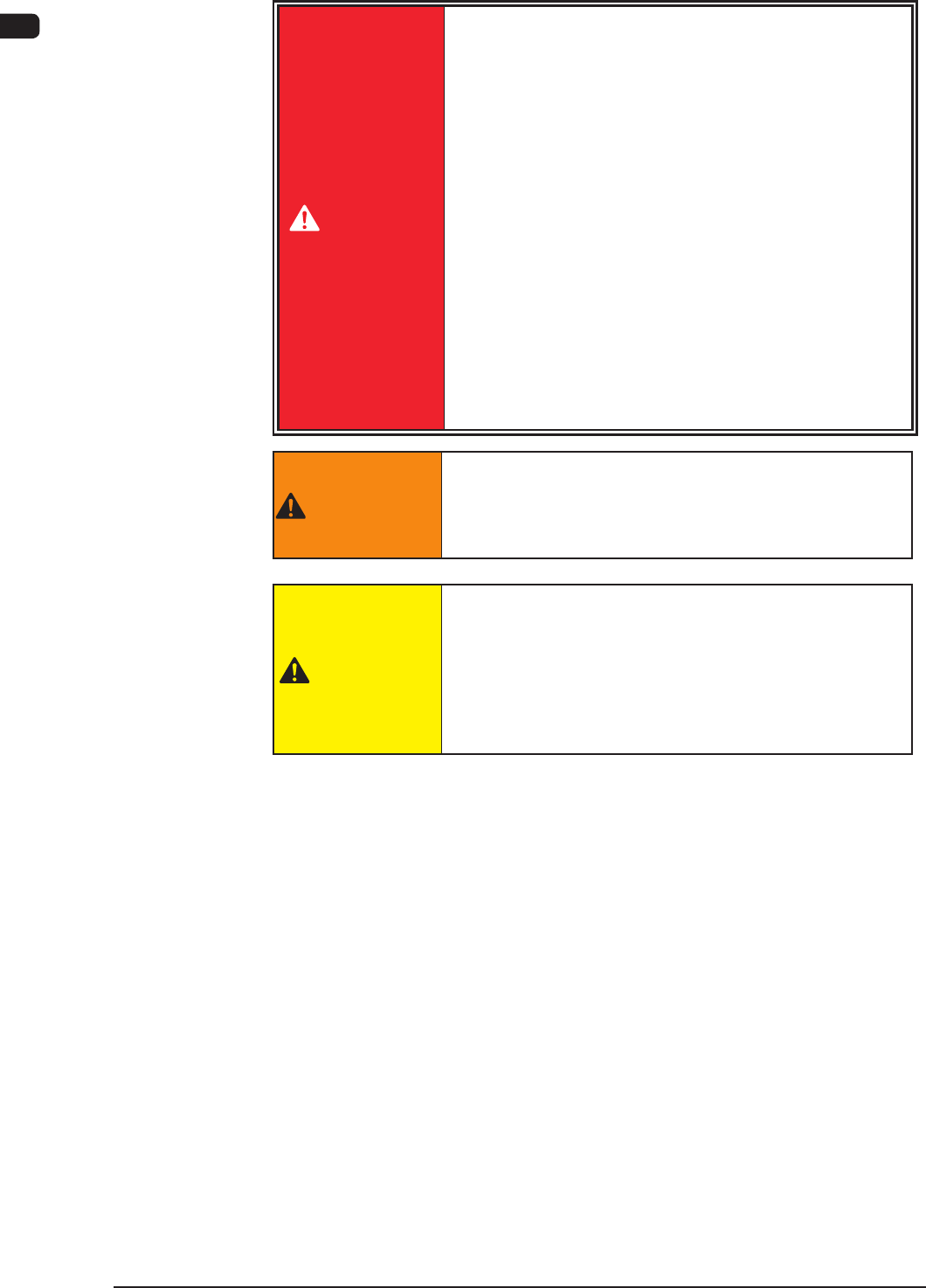
2.2.3 Cover Section
DANGER
There are strong motorized and high-voltage areas
inside the machine. Special caution should be paid
not to touch them.
Doing otherwise will cause personal injury (serious
accident).
•
Only qualified maintenance personnel should
detach the covers.
•
The machine should be operated with the covers
being attached.
•
If a cover is detached, be sure to reattach it.
•
Be sure to close the transparent covers (door
type) before operating the machine.
•
Do not disengage the interlock mechanism of the
transparent covers (door type).
WARNING
Be sure to keep the all
transparent covers closed to
avoid any danger when the automatic operation is
started or during the automatic operation.
CAUTION
Avoidhandandngerinjuries.
•
Be careful to avoid hand and nger injuries when
closing the transparent covers.
•
Hold the handgrip rmly and open or close the cover
slowly.