ED-7306_E.pdf - 第10页
JEITA ED-7306 - 8 - 7. Recommended datasheet for th e package w arpage 7.1 Measurement temperatures for data sheet Typical measurement tem peratures for datasheet ar e ro om temperature, melting point, pea k temperature,…
JEITA ED-7306
- 7 -
5.3.2 Laser reflection method
Solder balls shall be removed when the solder ball pitch is not large enough for laser beam to measure the
warpage on the substrate surface. Samples are placed on the measurement table. The displacement from
the flatness is measured by the laser displacement sensor. The warpage is generally measured by
scanning the laser beam over the terminal lands or between balls throughout the measuring zone. The grid
pitch of the measurement points is preferably less than the solder ball pitch. The instrument is capable of
setting the measuring zone and measuring the warpage at elevated temperatures including the peak
temperature.
5.3.3 Data analysis (Data table, Diagonal scan graph, 3D plot graph)
The magnitude of the warpage is obtained from the data table of the measurements or 3D plot graph
(warpage distribution diagram over the measuring zone). Then the sign of the warpage (warpage direction)
is determined from the diagonal scan graph and precedes the value.
6. Maximum permissible package warpage at elevated temperature
The criteria of the maximum permissible package warpages for BGA and FBGA are specified in Table 1,
and those for FLGA are specified in Table 2.
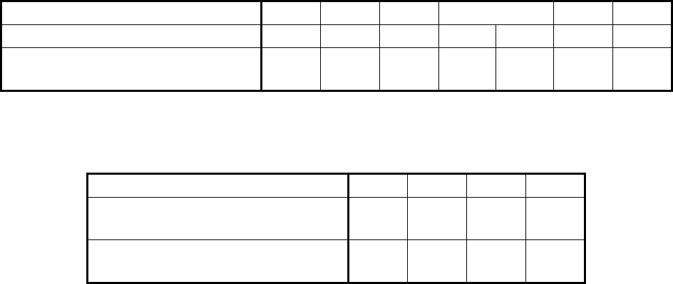
Table 1 Maximum permissible package warpages for BGA and FBGA
Unit: mm
Solder ball pitch 0.4 0.5 0.65 0.8 1.0 1.27
Condition of ball height 0.20 0.25 0.33 0.35 0.40 0.50 0.60
Maximum permissible package warpage
(Absolute value)
0.10 0.11 0.14 0.17 0.17 0.22 0.25
Table 2 Maximum permissible package warpages for FLGA
Unit: mm
Land pitch 0.4 0.5 0.65 0.8
Condition of thickness of molten solder
paste
0.08 0.10 0.11 0.13
Maximum permissible package warpage
(Absolute value)
0.08 0.10 0.11 0.13
JEITA ED-7306
- 8 -
7. Recommended datasheet for the package warpage
7.1 Measurement temperatures for data sheet
Typical measurement temperatures for datasheet are room temperature, melting point, peak temperature,
solidification point, and room temperature after cooling.
7.2 Datasheet
Datasheet is composed of
- temperature dependency of the package warpage (See Fig. 7),
- surface topography at each temperature in 3D plots (optional). (If the sign of warpage is opposite,
explanation is required; See Fig. 8),
- diagonal profile of the package at each temperature (optional). (If the sign of warpage is opposite,
explanation is required; See Fig. 8),
- explanatory figure of the sign of the package warpage (optional), and
- temperature profile for measurement.
7.3 Example of datasheets
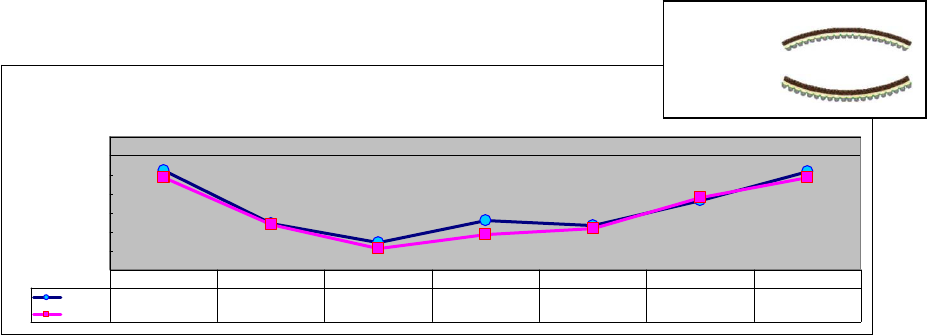
Fig. 7 Temperature dependency of the package warpage
Average warpage
for xxxx & yyyy
-70
-60
-50
-40
-30
-20
-10
0
Warpage(um)
xxxxAVG
-17.8 -46 -55.7 -44 -47 -33.8 -18.3
yyyy
AVG
-21.5 -46.2 -58.7 -51.8 -48.5 -32 -21.8
25C 150C 220C 260C 220C 150C 25C
+/
-
Sign
+
-
Warpage(µm)
0
-10
-20
-30
-40
-50
-60
-70
25°C 150°C 220°C 260°C 220°C 150°C 25°C
JEITA ED-7306
- 9 -
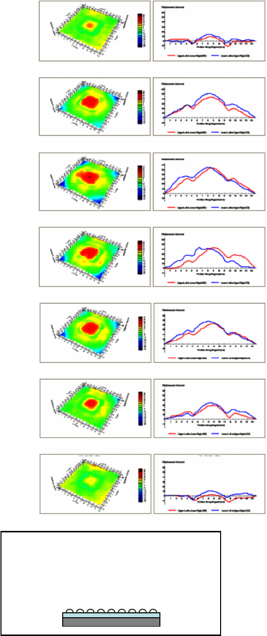
Fig. 8 Recommended datasheet
NOTE: The signs in the 3D plots and in the
diagonal profile are opposite from the
package warpage sign due to the dead
bug position in the measurement.
(150°C)
(Preheat temperature)
(For reference)
220°C
Melting point
260°C
Peak temperature
220°C
Solidification point
(150°C)
(Tg of PWB)
(For reference)
Room temperature
Room temperature