00193790-01.pdf - 第100页
2 English Installat ion and Getting Started with CACCIA 2.7 Connecting CACCIA with SIPLACE Issue 07/2004 34 The Select Machine dial og box will open and you can s elect the requi red SIPLACE ma chine: Fig. 2 - 29 CACCIA …
Installation and Getting Started with CACCIA 2 English
Issue 07/2004 2.7 Connecting CACCIA with SIPLACE
33
The table below lists the various CAN cards and their corresponding nets.
→ Once you have entered the required data, confirm your entries with Save Settings.
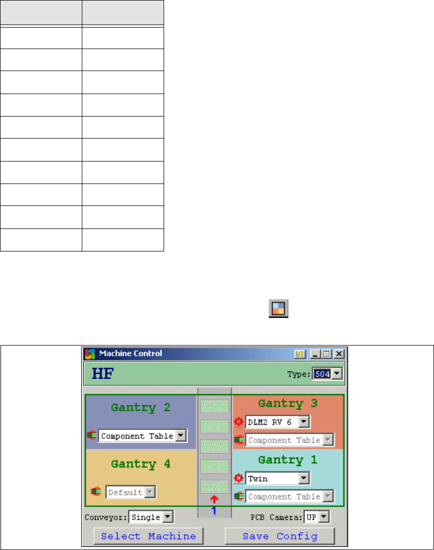
→ Now configure the SIPLACE machine by clicking on the icon in the main view. The
Machine Control dialog box will open:
Fig. 2 - 28 CACCIA - Machine Control
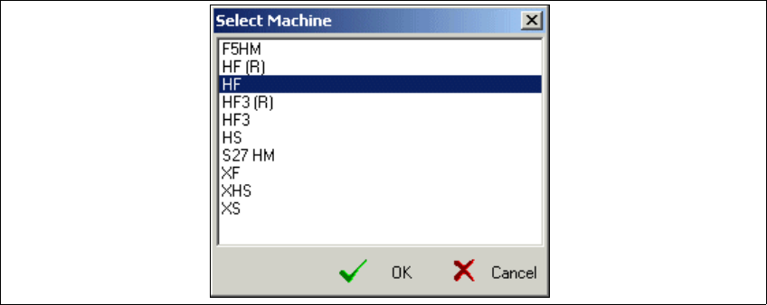
→ Click on Select Machine.
CAN card Net
ESD 2
SIE 2
KVASER 2
CANDY 1
CANBLUE 1
PCAN 1
SOFTING 2
CANAS 2
USBCAN 1
KVASER-USB ?
Table: CAN Card - Net
2 English Installation and Getting StartedwithCACCIA
2.7 Connecting CACCIA with SIPLACE Issue 07/2004
34
The Select Machine dialog box will open and you can select the required SIPLACE machine:
Fig. 2 - 29 CACCIA - Select Machine
→ Select the relevant machine and confirm your choice with OK.
A selection menu for configuration of individual machine subsystems will appear in the
Machine Control dialog box. The list boxes will only show those subsystems available for the
selected machine.
→ If you have chosen the SIPLACE HF machine, you will also need to select thesoftware version
installed on the machine from the Type list box.
→ Select the correct head type for each gantry and the appropriate component table.
→ Select the conveyor type for the chosen machine from the Conveyor list box.
→ Select the camera for the chosen machine from the PCB Camera list box. The following op-
tions are available:
–UP
Under-gantry camera (standard PCB camera)
–MC
Multicolor camera
→ Once you have entered the required data, confirm your entries with Save Config.
Installation and Getting Started with CACCIA 2 English
Issue 07/2004 2.7 Connecting CACCIA with SIPLACE
35
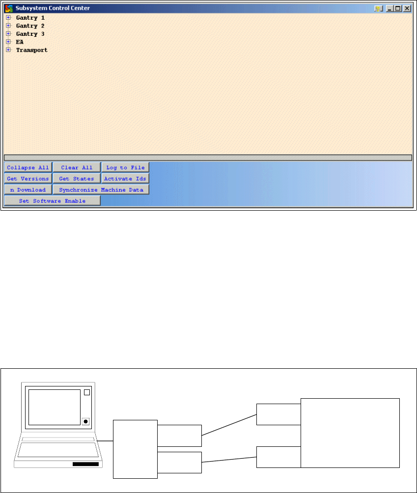
→ The Subsystem Control Center dialog box will open.
Fig. 2 - 30 CACCIA - Subsystem Control Center
→ This dialog box shows the subsystems as configured.
→ Now connect CACCIA to the SIPLACE machine.
→ The CAN service plugs for nets 1 and 2 can be found in the control unit.
→ Connect the CAN bus cable to the COM card of the SIPLACE machine, in line with the CAN
bus structure. For a detailed description of the CAN bus structure see “Overview of the CAN
Bus Structure in SIPLACE Machines” on page 4.
→ You can now work with the CACCIA service and monitoring software.
Fig. 2 - 31 Example: CACCIA with SIPLACE
SIPLACE
network 1
network 2
CAN card for
the laptop
PCMCIA
network 1
network 2
CACCIA