00193790-01.pdf - 第105页
Installation and Getting Started with CACCIA 2 English Issue 07/2004 2.9 Online Help 39 2.9 Onli ne H elp The On line Help tool prov ides de tailed infor mation abo ut using CACC IA. CACC IA has the foll owin g inf ormat…

2 English Installation and Getting StartedwithCACCIA
2.8 CACCIA - Program Overview Issue 07/2004
38
2.8.1.6 Firmware Download
The Download dialog box will open. Firmware downloads can be started here. Users
can select either a segment ID download or a channel ID download.
2.8.1.7 Change Properties
The Advanced Subsystem Configuration dialog box will open. The CAN card you are
working with can be configured here.
2.8.1.8 Change Machine Configuration
The Machine Control dialog box will open. You can select the relevant SIPLACE
machine and configure its subsystems here.
2.8.1.9 Open Subsystem Control
The Subsystem Control Center dialog box will open. All subsystems will be shown for
the configured machine. A separate dialog box can be opened for each subsystem.
Various functions for the individual subsystems can be started from this dialog box e.g.
firmware download, status request for all sybsystems.

Installation and Getting Started with CACCIA 2 English
Issue 07/2004 2.9 Online Help
39
2.9 Online Help
The Online Help tool provides detailed information about using CACCIA. CACCIA has the
following information access options.
2.9.1 Knowledge-Based Online Help
Open the submenu Contents and Index from the Help menu.
You can either jump directly to a specific topic via Contents and Index or use the Search
functions.
Key information about using CACCIA is listed here.
2.9.2 Help Buttons
A Help button is provided for each dialog.
Click on the Help button to open the corresponding help information for the whole dialog.
2 English Installation and Getting StartedwithCACCIA
2.10 Overview of the Jumper Settings for Individual Subsystems Issue 07/2004
40
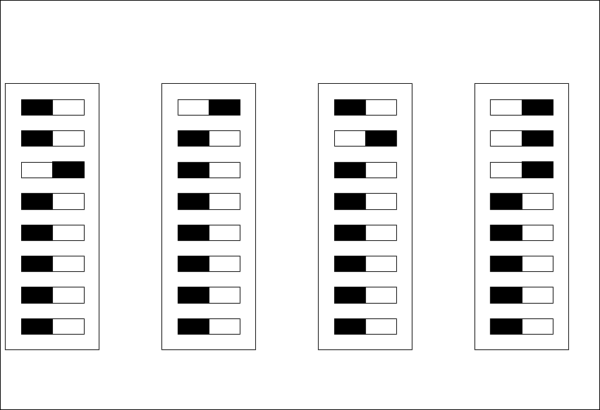
2.10 Overview of the Jumper Settings for Individual
Subsystems
2.10.1 SIPLACE HF3: Gantry
2.10.1.1 DIP Switches on the Head Interface
Legend
(1) P0 - Gantry address switch 1
(2) P1 - Gantry address switch 2
(3) CAN R - CAN terminator (at Twin option always OFF)
(4) Boot - CAN Processor 16 Bit not mounted
(5) Reset - CAN Processor 16 Bit not mounted
(6) C0 - CAN Address switch
(7) C1 - CAN Address switch
(8) WPE - Write protect enable at the moment OFF
DIP Switch
ON
78123456
ON
78123456
ON
78123456
ON
78123456
Gantry 1
Gantry 2
not used
Gantry 3 Gantry 4
C&P Head
C&P Head
Twin Head