00193790-01.pdf - 第109页
Installation and Getting Started with CACCIA 2 English Issue 07/2004 2.10 O verview of the J umper Settings for Individual Subsystems 43 Descript ion LED‘S and DIP switches on the head i nterface: LED 1-7 (functional che…
2 English Installation and Getting StartedwithCACCIA
2.10 Overview of the Jumper Settings for Individual Subsystems Issue 07/2004
42
2.10.2 SIPLACEHF3:DescriptionoftheSwitchesandPCBBoardsontheC&PHead
2.10.2.1 Head Interface
The same head interface board will be use on gantry 1 and gantry 2 for the Twin head and C&P
head.
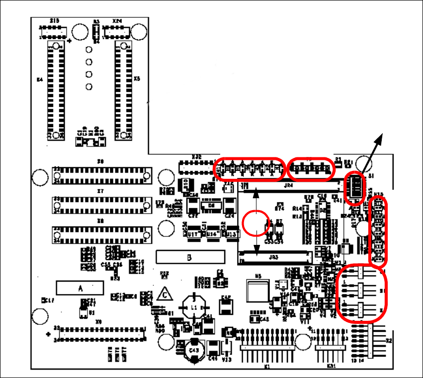
Fig. 2 - 33 Head interface
Legend
(1) X11 Connector Temperature sensor X-Axis
(2) X17 Connector BERO Travel range X-Axis
(3) X16 Connector BERO Travel range X-Axis
(4) X15 Connector for incremental encoder X-Axis
(5) X24 Test connector digital track signals X-Axis
(6) Connector for "One wire" Processor board
LED 1-7 TP 1-8
LED 1-10
DIP Switch
1
2
3
4
5
6
Installation and Getting Started with CACCIA 2 English
Issue 07/2004 2.10 Overview of the Jumper Settings for Individual Subsystems
43
Description
LED‘S and DIP switches on the head interface:
LED 1-7 (functional check)
– SPI - Serial parallel interface (A/D or D/A converter in future)
– D-ON - Digital ON 5V DC/DC Converter
– H-OK - Head adapter board connected
– C-In - CAN Internal not used
– MRST - Main Reset
–F-UC- notused
– MP - Main Power fail, mean 5 V power supply being missing at the machine
(e.g. CAN Bus)
LED 1-10 (LED´s for voltages)
– Vcc - Power supply +5 V head interface
– N15V - Minus 15 Volt (from the Axis unit → Error → LED red)
– P3,3V - Not used
– P15V - Plus 15 Volt (from the Axis unit → Error → LED red)
– P24V - 24 Volt power supply (e.g. stepper motor)
–AVER-Notused
– ENAN- Notused
– P5V - 5 Volt Power supply track signals X-Axis → ON Power fail
– VccF - 5 Volt for digital
– TMP - Temperature monitoring X-Axis
2 English Installation and Getting StartedwithCACCIA
2.10 Overview of the Jumper Settings for Individual Subsystems Issue 07/2004
44
2.10.2.2 Vision Board (analog)
The vision board is connected on the top of the head interface. That board is used on the gantry
with a C&P head and Twin head.
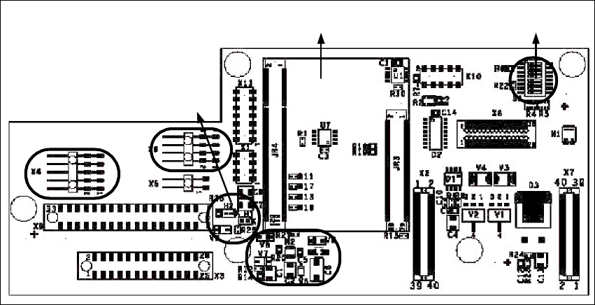
Fig. 2 - 34 Vision board
Legend
(1) Connector illumination PCB camera
(2) Connector PCB camera
(3) LED‘s P15V - 15Volt / Vcc - Power supply vision board
(4) DIP Switch
(5) CAN Processor 16 Bit (additional board on the vision board)
(6) DC/DC Converter 15 → 5V for visionsystem.
4
5
1
3
2
6