00193790-01.pdf - 第124页
2 English Installat ion and Getting Started with CACCIA 2.10 Overview of the J umper Settings for Individual Subsyst ems Issue 07/2004 58 Legend (1) Conn ector fo r FC ca mera ill uminatio n (2) Conn ector fo r IC c amer…
Installation and Getting Started with CACCIA 2 English
Issue 07/2004 2.10 Overview of the Jumper Settings for Individual Subsystems
57
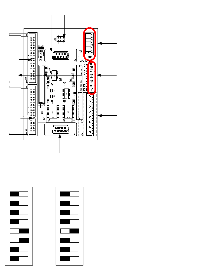
2.10.3.6 Vision Control Board "IC camera"
The vision control board is installed in sector 2 for the Twin head on gantry 3 and at sector 4 for
the Twin head on gantry 1 (only for SIPLACE HF).
Fig. 2 - 46 Vision control board IC camera
1
6
3
4
5
2
7
8
9
to 5)DIP Switch
(1) CAN Terminator
(2) RESET
(3) Bootstrap
(4) TEST
(5) P1 Address Switch
(6) P0 Address Switch
(7) CAN - ID 1
(8) CAN - ID 0
DIP Switch
ON
78123456
ON
78123456
Gantry 1
for HF
Gantry 2
for HF/HF3
2 English Installation and Getting StartedwithCACCIA
2.10 Overview of the Jumper Settings for Individual Subsystems Issue 07/2004
58
Legend
(1) Connector for FC camera illumination
(2) Connector for IC camera illumination
(3) Service connector
(4) LED‘s (downwards D4 - D1)
– + 5V/-15V/+15 V / +40 V
(5) DIP Switch
(6) Connector CAN Bus
(7) Power supply vision control board
Connector for DC/DC converter (Section2)
for DC/DC distributor (section 4)
(8) Connectors for CAN Bus Processor 16 Bit
(9) Flash signal

Installation and Getting Started with CACCIA Index
Issue 07/2004
59
Index
A
AccessingtheLicenseInformation ...........16
ActivatingtheLicense.....................14
Additionalequipment .....................11
Administrationrights .................. 12
, 13
Advanced Subsystem Configuration . . . . . . . . . .38
Advanced Subsystems Configuration . . . . . . . . .32
applyforalicense........................14
AutomaticUpdateInstallation ...............27
AvailablePCMCIAslot ....................12
B
BaseConverter..........................37
basicfunctions ..........................14
Buttons
Help ...............................39
C
CACCIA-ProgramOverview ...............36
CACCIAFunctions .......................36
CACCIAInstallation ......................18
Calculator ..............................37
CANassemblies ..........................3
CANbuscable ..........................11
CAN Bus Structure in
SIPLACEHF3Machines ............. 6
, 7
CANcard-net ..........................33
CANcardforlaptop ......................11
CANcardforPC .........................11
CANProcessorboard16Bit................45
CANProcessorboard8Bit .................48
CANProcessorboard16Bit ................53
CANScope .............................37
CANSelftest ............................37
CANserviceplugs .......................35
CD-ROMdrive ..........................12
CommandTestCenter ....................37
ConfigurationofCACCIA ..................19
ConnectingCACCIAwithSIPLACE ..........32
controlunit .............................35
D
DescriptionLED‘SontheHeadinterface ..... 43
DIP Switches on the head interface . . . . . .... 40
DIP Switches on the vision board . . . . . . . .... 41
Diskettedrive .......................... 12
downloadfunctions ...................... 14
E
ESDassemblies ........................ 10
ESDguidelines ......................... 10
F
F5HMmachines......................... 9
F5HM ................................. 3
FirmwareDownload ..................... 38
Flatribboncable ........................ 11
H
Handling the machine . . . ................. 10
Hardware ............................. 12
HardwareID ........................... 15
HeadadapterTwinHead ................. 54
Headinterface.......................... 50
Headadapter for 6/12 C&P head . . . . . . . . .... 46
Headinterface . . . . . . . . . ................. 42
Helpbuttons ........................... 39
HF .................................... 3
HF(R) ................................. 3
HF3 ................................... 3
HF3(R) ................................ 3
HS.................................... 3