00193790-01.pdf - 第70页
2 English Installat ion and Getting Started with CACCIA 2.1 General Issue 07/2004 4 2.1.2 Ove rview of the CAN Bus Struc ture in SIPLA CE Machines 2.1.2.1 Overvie w of the CAN Bus S tructure i n SIPLACE HF Machines up to…
Installation and Getting Started with CACCIA 2 English
Issue 07/2004 2.1 General
3
2 English
2.1 General
This document describes CACCIA. Before beginning work please read this manual carefully. It
contains installation instructions and other important information. These instructions are directed
at persons installing and operating CACCIA.
You will find the following information in this manual:
– Target group and safety
– System requirements
– Instructions for the installation of CAN cards (PC and laptop)
– Instructions for the installation of CAN drivers (PC and laptop)
– Instructions for the installation of CAN software
– Description of CACCIA functions
– Overview of the Online Help function
2.1.1 What is CACCIA?
CACCIA is a service and monitoring software for the individual CAN assemblies in SIPLACE
machines.
The following SIPLACE machines are supported:
– SIPLACE F5HM
– SIPLACE HF (R)
– SIPLACE HF
– SIPLACE HF3 (R)
– SIPLACE HF3
– SIPLACE HS
– SIPLACE S-27 HM
2 English Installation and Getting StartedwithCACCIA
2.1 General Issue 07/2004
4
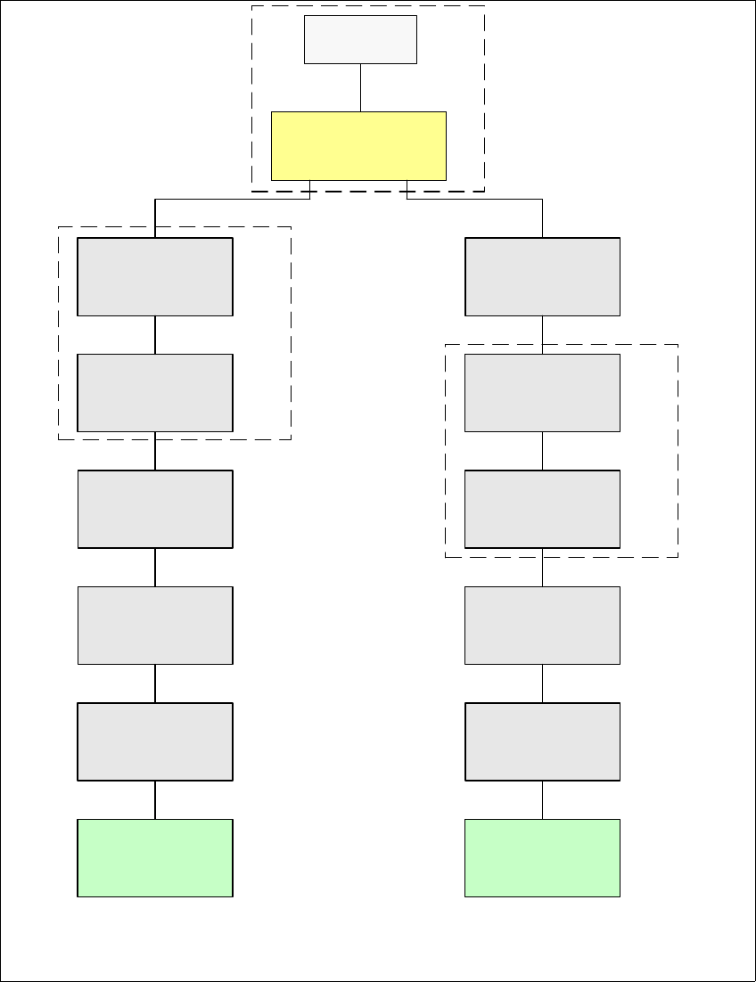
2.1.2 Overview of the CAN Bus Structure in SIPLACE Machines
2.1.2.1 Overview of the CAN Bus Structure in SIPLACE HF Machines up to MA.No. A001
Fig. 2 - 1 Overview of the CAN Bus Structure in SIPLACE HF Machines (only up to MA No. A001)
SMP BUS
COM Unit
MC
MC
Axis unit
PA 2
Trailing cable-
Interface
Gantry 1
Trailing cable-
Interface
Gantry 2 *
CAN Bus cable 2
CAN E/
A
Modu
l
Sektor 4
CAN E/
A
Modu
l
Sektor 4
CAN E/
A
Modu
l
Sektor 4
CAN I/O
SUB Module
Section 4
Vision
Section 2
COT 2 / MTC
Tape cutter
Transport
Control
unit
Vision
Control unit
CAN I/O
Main Module
COT 1
Tape cutter
COT 3
Tape cutter
BE-Tisch 4 / MTC
Gurtschneider
CAN Bus cable 1
Computer Unit
SUB Distributor Section 4
Main Distributer Sektor 4
Section 4
Control unit
Section 2
* SW Update 504 --> 505 Gantry 2 will be changed to gantry 3
Installation and Getting Started with CACCIA 2 English
Issue 07/2004 2.1 General
5
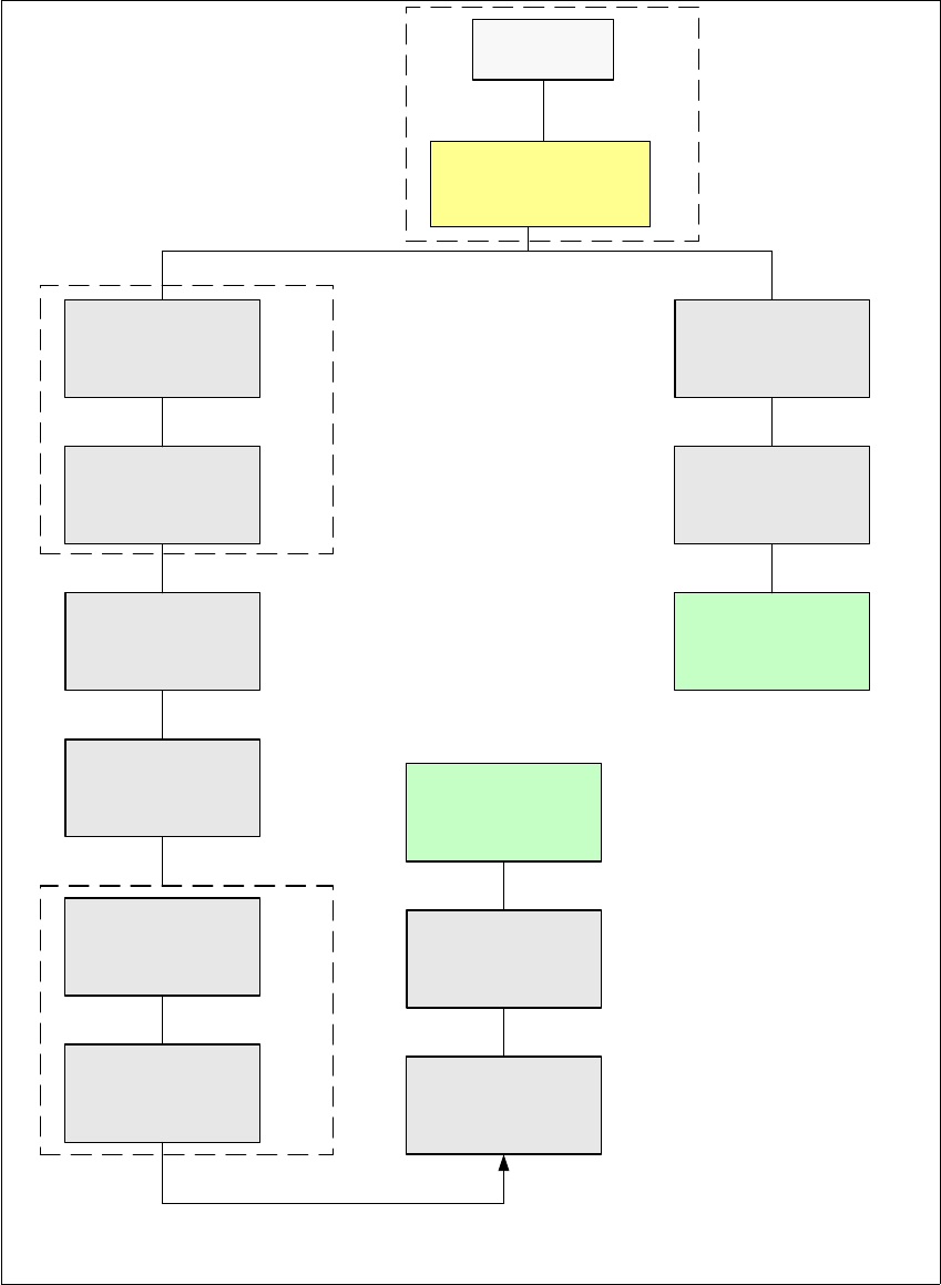
2.1.2.2 Overview of the CAN Bus Structure in SIPLACE HF Machines from MA.No. A001
Fig. 2 - 2 Overview of the CAN Bus Structure in SIPLACE HF Machines (from MA No. A001)
SMP BUS
COM Unit
MC
MC
Axis unit
PA 2
Trailing cable-
Interface
Portal 1
CAN Bus cable
COT 3
Tape cutter
Computer Unit
* SW Update 504 --> 505 Gantry 2 will be changed to gantry 3
Trailing cable-
Interface
Gantry 2 *
Transport
COT 2 / MTC
Tape cutter
CAN E/
A
Modu
l
Sektor 4
CAN E/
A
Modu
l
Sektor 4
CAN E/
A
Modu
l
Sektor 4
CAN I/O
SUB Module
Section 4
Vision
Control unit
COT 1
Tape cutter
COT 4 / MTC
Tape cutter
SUB Distributor Section 4
Vision
Section 2
CAN I/O
Main Module
Section 2
Main Distributor Section 4
Section 4
Control unit
Control unit