00193790-01.pdf - 第72页
2 English Installat ion and Getting Started with CACCIA 2.1 General Issue 07/2004 6 2.1.2.3 Overvie w of the CAN Bus S tructure i n SIPLACE HF3 Machines Fig. 2 - 3 Overview of the CAN Bus Structure in SIPLACE HF3 Machine…
Installation and Getting Started with CACCIA 2 English
Issue 07/2004 2.1 General
5
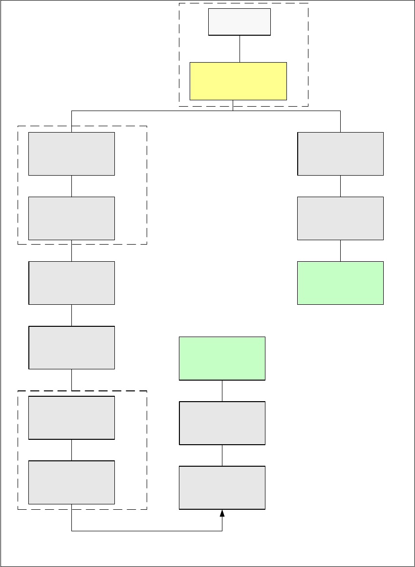
2.1.2.2 Overview of the CAN Bus Structure in SIPLACE HF Machines from MA.No. A001
Fig. 2 - 2 Overview of the CAN Bus Structure in SIPLACE HF Machines (from MA No. A001)
SMP BUS
COM Unit
MC
MC
Axis unit
PA 2
Trailing cable-
Interface
Portal 1
CAN Bus cable
COT 3
Tape cutter
Computer Unit
* SW Update 504 --> 505 Gantry 2 will be changed to gantry 3
Trailing cable-
Interface
Gantry 2 *
Transport
COT 2 / MTC
Tape cutter
CAN E/
A
Modu
l
Sektor 4
CAN E/
A
Modu
l
Sektor 4
CAN E/
A
Modu
l
Sektor 4
CAN I/O
SUB Module
Section 4
Vision
Control unit
COT 1
Tape cutter
COT 4 / MTC
Tape cutter
SUB Distributor Section 4
Vision
Section 2
CAN I/O
Main Module
Section 2
Main Distributor Section 4
Section 4
Control unit
Control unit
2 English Installation and Getting StartedwithCACCIA
2.1 General Issue 07/2004
6
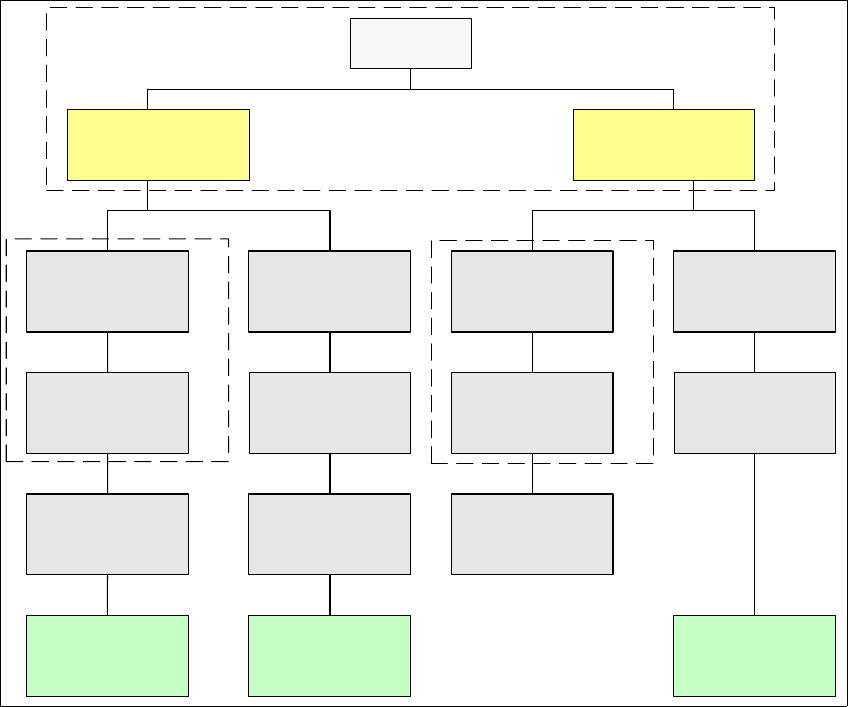
2.1.2.3 Overview of the CAN Bus Structure in SIPLACE HF3 Machines
Fig. 2 - 3 Overview of the CAN Bus Structure in SIPLACE HF3 Machines
SMP BUS
COM Unit
(Left)
MC
MC
Axis unit
BB 1
Trailing cable-
Interface
Gantry 1
CAN Bus cable
COT 3
Tape cutter
Computer Unit
Transport
Control unit
COT 2 / MTC
Tape cutter
CAN E/
A
Modu
l
Sektor 4
CAN E/
A
Modu
l
Sektor 4
CAN E/
A
Modu
l
Sektor 4
CAN I/O
SUB Module
Section 4
Vision
Control unit
COT 1
Tape cutter
COT 4
Tape cutter
SUB Distributer Section 4
Vision
Section 2
CAN I/O
Main Module
Sektor 2
Main Distributer Section 4
COM Unit
(Right)
Axis unit
BB 2
Section 4
Control unit
Trailing cable-
Interface
Gantry 4
Trailing cable-
Interface
Gantry 3
Installation and Getting Started with CACCIA 2 English
Issue 07/2004 2.1 General
7
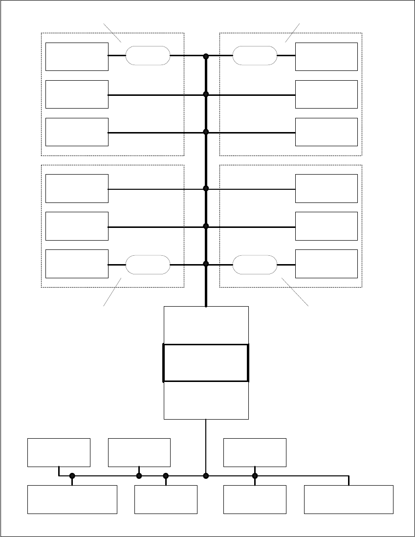
2.1.2.4 Overview of the CAN Bus Structure in SIPLACE HS-50 Machines
Fig. 2 - 4 Overview of the CAN Bus Structure in SIPLACE HS-50 Machines
Component
Table 4
Tape Cutter 4
Head Gantry 4
Head Gantry 3
Tape Cutter 3
Component
Table 3
Machine
Controller
CAN assembly 2
125 kbps CAN bus
CAN assembly 1
500 kbps CAN bus
Decoupling
Unit
Decoupling
Unit
Component
Table 2
Tape Cutter 2
Head Gantry 2
Decoupling
Unit
Decoupling
Unit
Head Gantry 1
Tape Cutter 1
Component
Table 1
SLIO 1 SLIO 2
SLIO 3
( optional)
Conveyor Controller 1
SLIO
Conveyor 1
SLIO
Conveyor 2
Conveyor Controller 2
Sector 1
Sector 3
Sector 4
Sector 2