196396 Iss 2 Nov 2015 - Semi Appendix Manual.pdf - 第17页
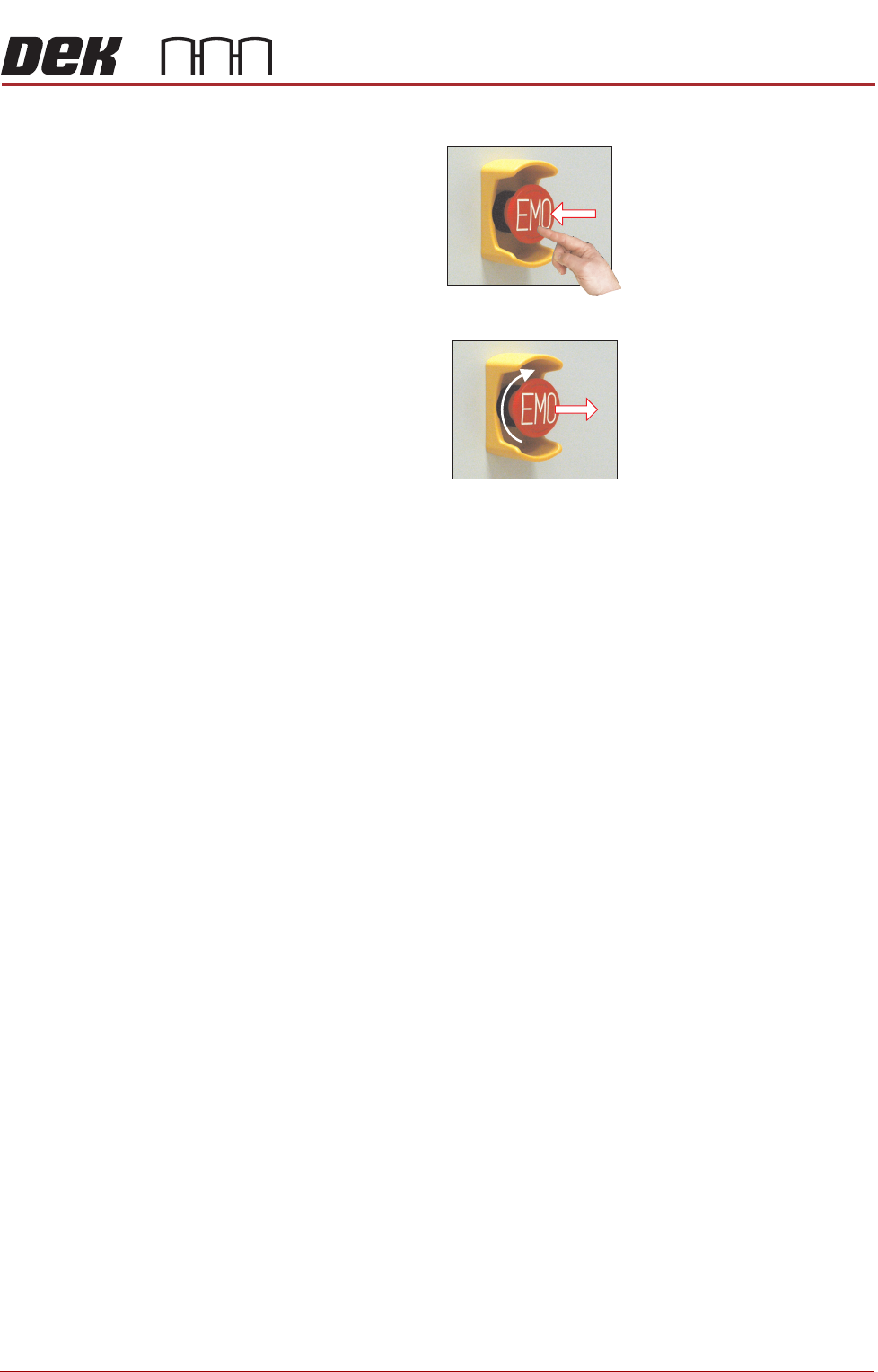
SAFETY FEATURES GENERAL Chapter Issue 4, Nov 14 Installation Manual 1.9 The EMO switch, once pressed, is a latching switch and requires resetting. Recovery T o reset the EMO, turn the button clockwi se until it unlatches…
SAFETY FEATURES
GENERAL
1.8 Installation Manual Chapter Issue 4, Nov 14
Two Button
Control Switches
The two button control switches or jog switches are positioned such as to
maintain maximum safety for the operator whilst solvent priming or paper
feeding with the printhead cover open. This requires both buttons to be
depressed simultaneously for the function to become active. The use of these
buttons is dependent on the function selected on the machine monitor. During
normal operation these buttons control paper feed and solvent prime opera-
tions. When in maintenance mode, the two button control switches control the
following diagnostics:
• Print Carriage
• Squeegee Assembly
• Camera Axes
• Rail System
• Screen Alignment
• Rising Table
Only one button is required to drive the selected mechanism, the two buttons
are used to drive the mechanism in opposite directions, ie jog forward or jog
back.
Emergency
Shutdown
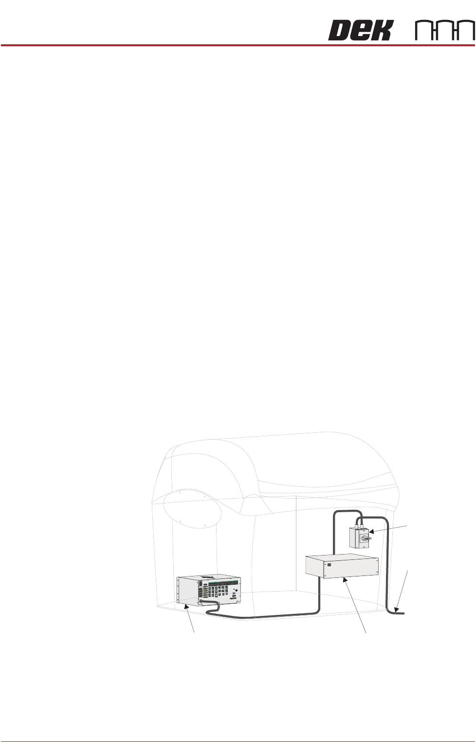
If an emergency stop is initiated via the EMO, all power and pneumatics to the
machine are removed. Electrical power remains to the M39 EMO enclosure via
the mains isolator but is removed from there to the M37 power supply unit.
Switching mains isolator to OFF removes electrical power from the M39 EMO
enclosure. Pneumatic supply is also closed off and any pressurised air remain-
ing within the machine’s system is vented via the pneumatic dump valve.
Figure 1-2 Mains Electrical Supply
From Factory
Mains Supply
Mains Isolator
Switch
M37 Power Supply Enclosure
M39 EMO Enclosure
SAFETY FEATURES
GENERAL
Chapter Issue 4, Nov 14 Installation Manual 1.9
The EMO switch, once pressed, is a latching switch and requires resetting.
Recovery To reset the EMO, turn the button clockwise until it unlatches.
Press the Start button, to restore electrical and pneumatic power to the
machine. When prompted by a screen message press the System button.
SAFETY FEATURES
LOCKOUT
1.12 Installation Manual Chapter Issue 4, Nov 14
LOCKOUT
Electrical Lockout
WARNING
LETHAL VOLTAGE. DANGEROUS VOLTAGES EXIST IN THIS EQUIPMENT.
ENSURE ALL ELECTRONIC COVERS AND MAIN MACHINE COVERS ARE
FITTED BEFORE OPERATING THIS EQUIPMENT.
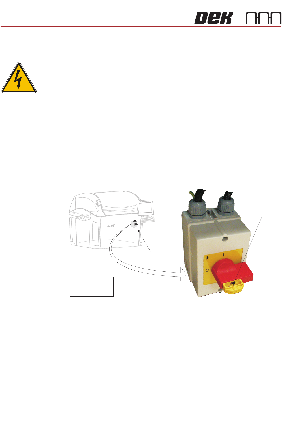
Electrical lockout of the machine is achieved by applying a padlock, or any other
suitable locking device, through the centre pull out section of the mains isolator
switch. This can only be achieved when the switch is in the OFF position.
To electrically lockout the machine, carry out the following procedure:
1. Close down the machine software.
2. Switch the mains isolator to the OFF position.
3. Pull the yellow centre section of the mains isolator switch out.
4. Fit a padlock or suitable locking device through the lockout point in the
centre section of the switch.
5. This completes the electrical lockout.
Mains Isolator Switch
NOTE
Switch shown in
the OFF position
Lockout Point