196396 Iss 2 Nov 2015 - Semi Appendix Manual.pdf - 第20页
SAFETY FEATURES SEMI - L EVE LS OF ELEC TR ICAL WO RK 1.14 Installation Manual Chapter Issue 4, N ov 14 SEMI - LEVELS OF ELECTRICAL WORK The t able below show the four levels of energized electrical wor k carried out on …
SAFETY FEATURES
LOCKOUT
Chapter Issue 4, Nov 14 Installation Manual 1.13
Pneumatic Lockout
WARNING
COMPRESSED AIR. COMPRESSED AIR SHOULD NEVER IMPINGE UPON THE
BODY. PORTS, PIPES, ETC MUST NEVER BE BLOCKED BY HAND. BEFORE
CONNECTING OR DISCONNECTING ANY PNEUMATIC COMPONENTS, ENSURE
THE COMPRESSED AIR SUPPLY HAS BEEN DISSIPATED AND DISCONNECTED
FROM THE MACHINE.
Pneumatic lockout of the machine is achieved by:
1. If the electrical lockout procedure has just been implemented, go to Step 4.
2. Close down the machine software.
3. Switch the electrical mains isolator to the OFF position.
4. Turn OFF the factory’s main pneumatic supply to the machine.
5. Dissipate remaining air in the pneumatic supply line.
6. Disconnect the pneumatic supply line from the machine.
7. This completes the pneumatic lockout.
SAFETY FEATURES
SEMI - LEVELS OF ELECTRICAL WORK
1.14 Installation Manual Chapter Issue 4, Nov 14
SEMI - LEVELS OF ELECTRICAL WORK
The table below show the four levels of energized electrical work carried out on
electrical equipment and its associated circuits, as defined by the SEMI S2-
0200 Standard.
Throughout all the ASM manuals when a maintenance or calibration procedure
falls within any of these four levels of energized electrical state, the appropriate
symbol is represented in the margin alongside that procedure.
A full definition can be found in the SEMI S2-0200 Safety Guidelines for
Semiconductor Manufacturing Equipment. See also NFPA 79-14.3, BS
EN60204, BS EN60950 and UL 1950.
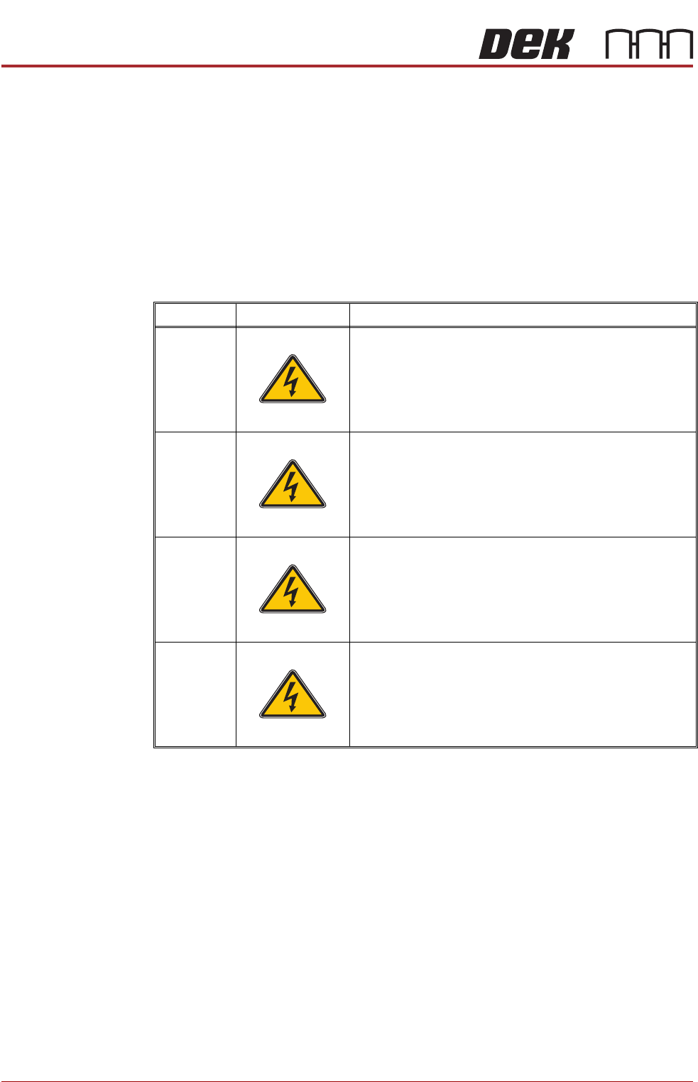
Type Symbol Definition
1
Equipment is fully de-energized
2
Equipment is energized. Energized circuits are cov-
ered or insulated. Work is performed at a remote
location to preclude accidental shock
3
Equipment is energized. Energized circuits are
exposed and accidental contact is possible. Potential
exposures are less than 30 volts rms, 42.4 volts peak
to peak, 60 volts dc, or 240 volt-amps in dry locations
4
Equipment is energized. Energized circuits are
exposed and accidental contact is possible. Potential
exposures are greater than 30 volts rms, 42.4 volts
peak to peak, 60 volts dc, 240 volt-amps in dry loca-
tions, or radio frequency (rf) is present
SEMI 1
SEMI 2
SEMI 3
SEMI 4
COVERS
PRINTER COVERS
Chapter Issue 4, Nov 14 Installation Manual 2.7
11. Under the rails locate the four pan-headed screws that secure the rail
brace.
12. Using a 4mm Allen key remove the screws and detach the rail brace from
the mounting blocks.
13. Stow the rail brace and screws away.
14. Under the rails locate the two shoulder bolts that secure the gate to the
mounting blocks.
15. Hold the gate assembly, using a 4mm Allen key remove the shoulder bolts
and lower the gate assembly away from the rails.
16. Stow the gate assembly away.
17. Under the rear rail locate the two outer pan-headed screws that secure the
rear mounting block. Hold the inner cover, using a 4mm Allen key
remove the two screws and lower the mounting block and the inner cover
away from the rear rail.
18. Stow the rear mounting block and the inner cover away.
Rear Printhead
Fixed Cover
To remove the rear printhead fixed cover, carry out the following:
1. Remove the rear panel.
2. Gain access to the rear of the EMO switch.
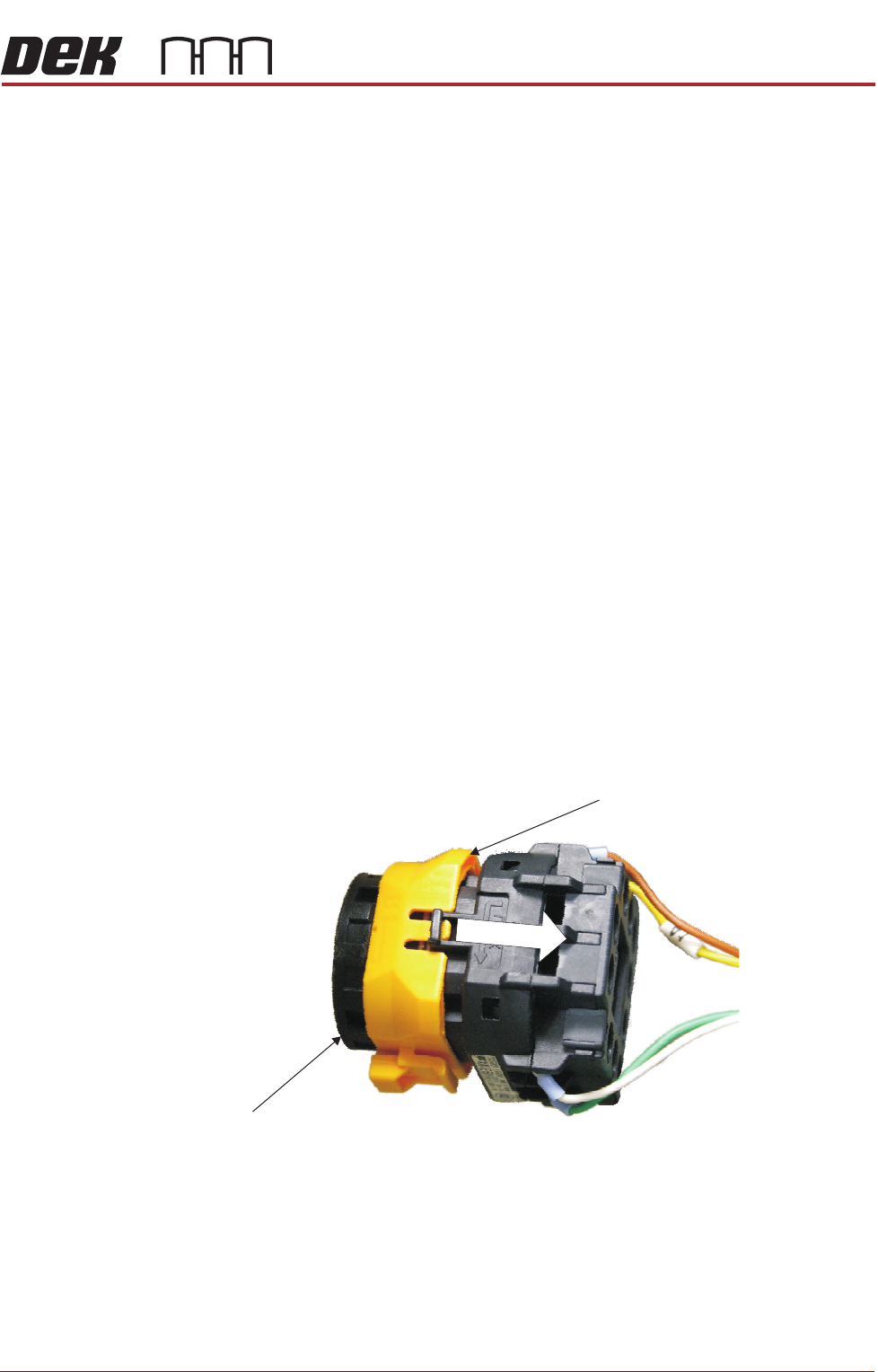
3. To disconnect the EMO carry out the following:
a. Locate the yellow locking collar at the rear of the switch.
b. Slide the collar rearwards towards the switch contact assembly against
spring pressure.
Locking Collar
EMO Switch
View on Rear EMO Switch