196396 Iss 2 Nov 2015 - Semi Appendix Manual.pdf - 第23页
COVERS PRINTER COVERS Chapter Issue 4, Nov 14 Installation Manual 2.9 5. The rear pr inthead cover is interlock ed with the upp er printhead cover using locati ng tabs. The rear printhead cove r must be lifted to allow t…
COVERS
PRINTER COVERS
2.8 Installation Manual Chapter Issue 4, Nov 14
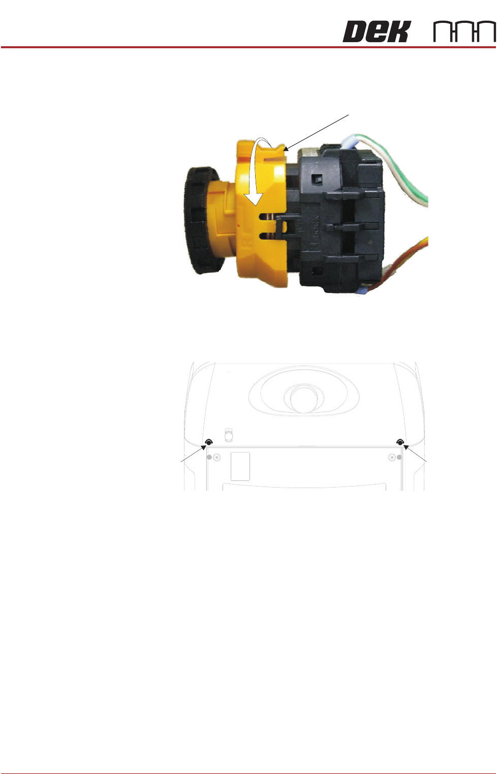
c. Viewed from the rear of the switch, rotate the locking collar anticlock-
wise to release the contact assembly from the switch body.
4. Release the two quarter-turn fasteners that secure the rear printhead
cover to the cover frame.
View on Rear EMO Switch
Locking Collar
Rear Printhead
Quarter-Turn
Fastener
Rear Printhead
Quarter-Turn
Fastener
COVERS
PRINTER COVERS
Chapter Issue 4, Nov 14 Installation Manual 2.9
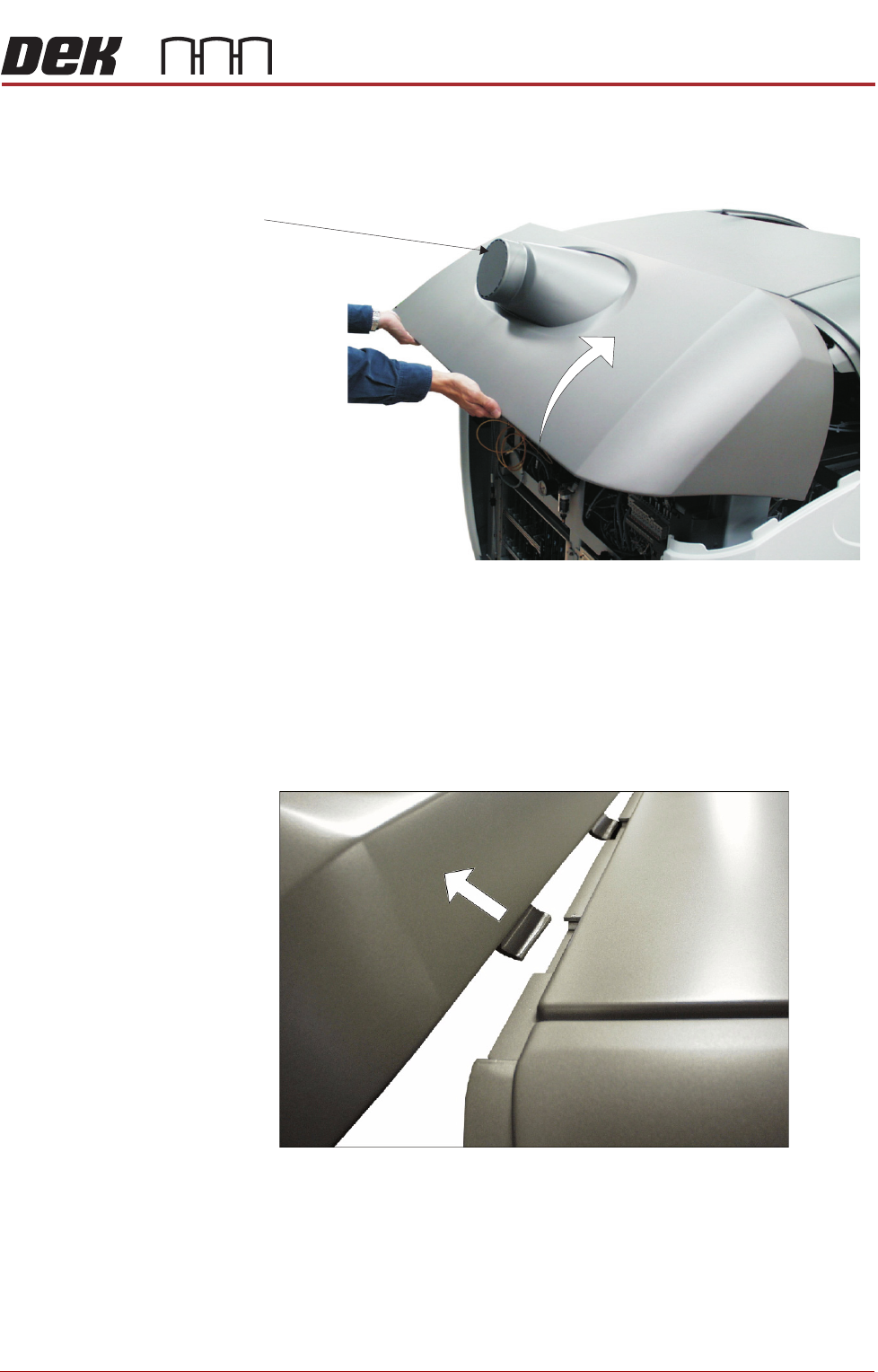
5. The rear printhead cover is interlocked with the upper printhead cover
using locating tabs. The rear printhead cover must be lifted to allow the
locating tabs to part.
NOTE
The knock out panel is removed when the printer is connected to a
Temperature Control Module (TCM). If a TCM is not fitted the knock out
panel must be intact, or this would contravene the safety requirements the
printer is tested to. Where the knock out panel has been removed and a
TCM is not fitted, ASM recommends fitting a new rear panel.
6. Once the locating tabs have cleared, pull the cover horizontally away from
the machine.
NOTE
Failure to assemble the rear EMO switch correctly results in the EMO
circuit remaining active preventing the machine from being powered up.
Upper Side Panels To remove the upper side panels, carry out the following:
1. Remove the rear printhead fixed cover (as detailed previously).
2. Open the front printhead cover.
Knock Out
Panel
COVERS
PRINTER COVERS
2.10 Installation Manual Chapter Issue 4, Nov 14
3. Remove the corresponding safety cover (as detailed previously).
NOTE
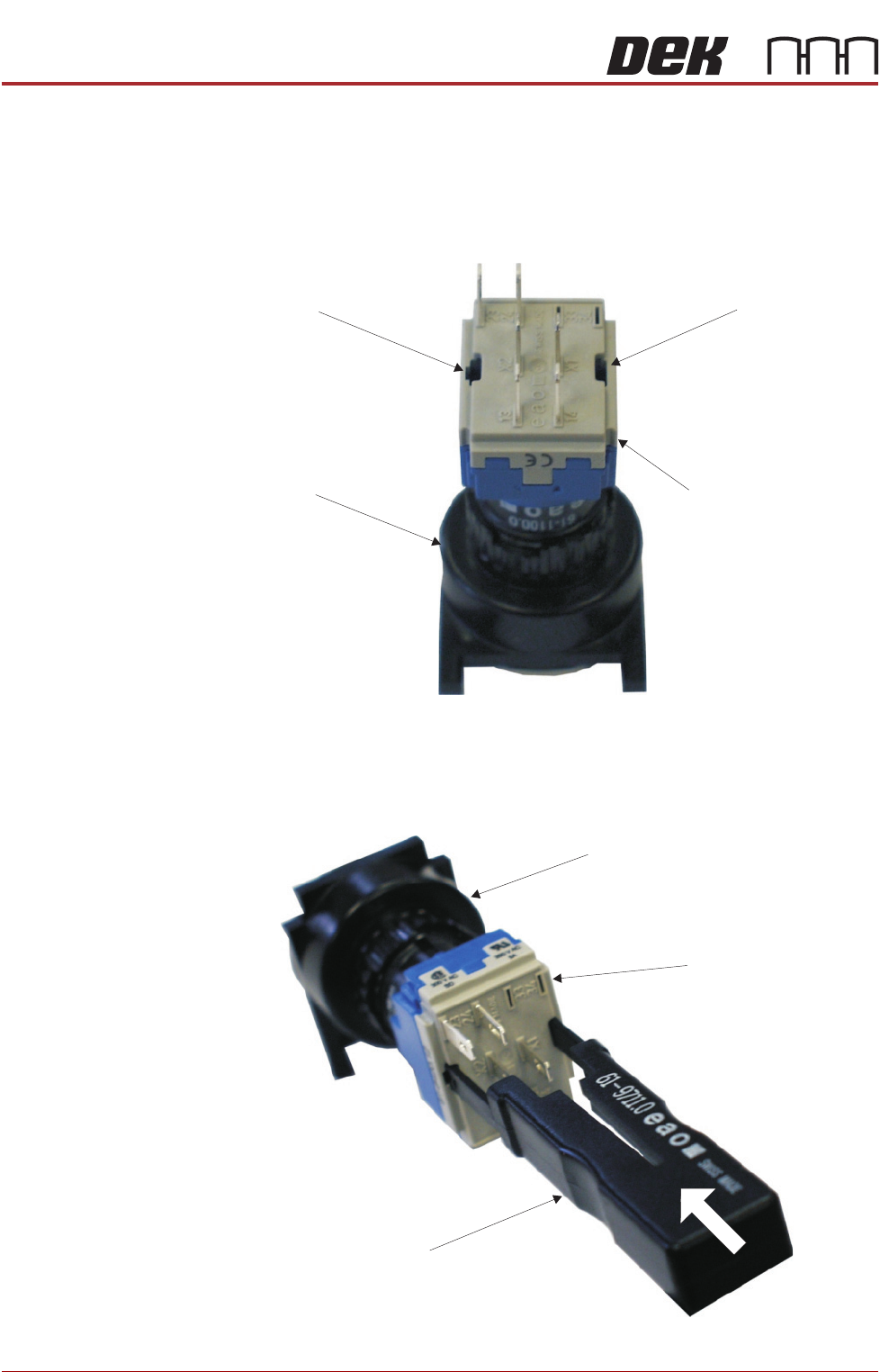
Before the upper side panel can be removed, the control switches (system
switch, jog switch etc.) must be disconnected in the following manner.
4. Locate the two release slots in the contact assembly part of the switch.
5. Insert the switch release tool (Part No 188647) into the slots and push until
the release tool clicks into place.
Contact AssemblySwitch Body
Release SlotRelease Slot
View on Rear of Switch
View on Rear of Switch
Switch Release Tool
Switch Body
Contact Assembly