196396 Iss 2 Nov 2015 - Semi Appendix Manual.pdf - 第26页
COVERS PRIN TER COVERS 2.12 Installation Manual Chapter Issue 4, N ov 14 3. T o remove the lef t hand front corner panel only , the front EMO swit ch must be disconnected. T o disconnect the EMO carry out the following: …
COVERS
PRINTER COVERS
Chapter Issue 4, Nov 14 Installation Manual 2.11
6. Leaving the switch release tool in position, pull the contact assembly from
the switch body.
7. Remove the switch release tool from the contact assembly.
NOTE
To refit the contact assembly to the switch body, using the locating keyway,
push the two units together until they click into place.
8. Release the three quarter-turn fasteners that secure the upper side panel
and remove the panel.
9. Repeat Steps 3 to 8 for the other side panel, if required.
Front Corner
Panels
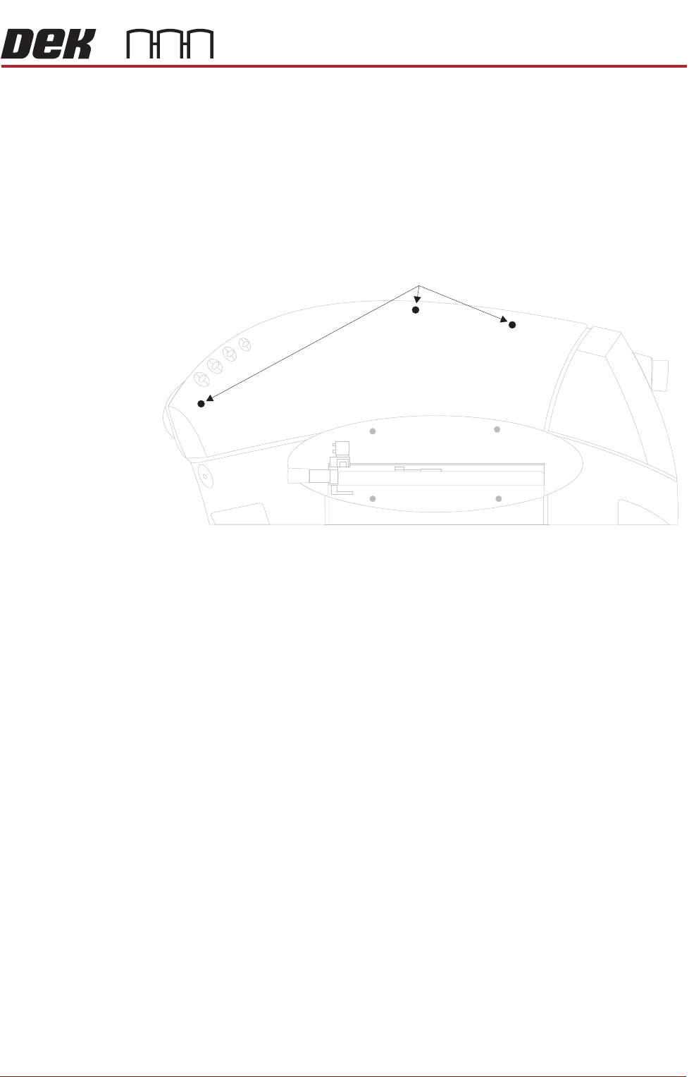
To remove the front corner panels, carry out the following:
1. Remove the front panel.
2. Remove the corresponding upper side panel (as detailed previously).
Upper Side Panel Quarter-Turn Fasteners
COVERS
PRINTER COVERS
2.12 Installation Manual Chapter Issue 4, Nov 14
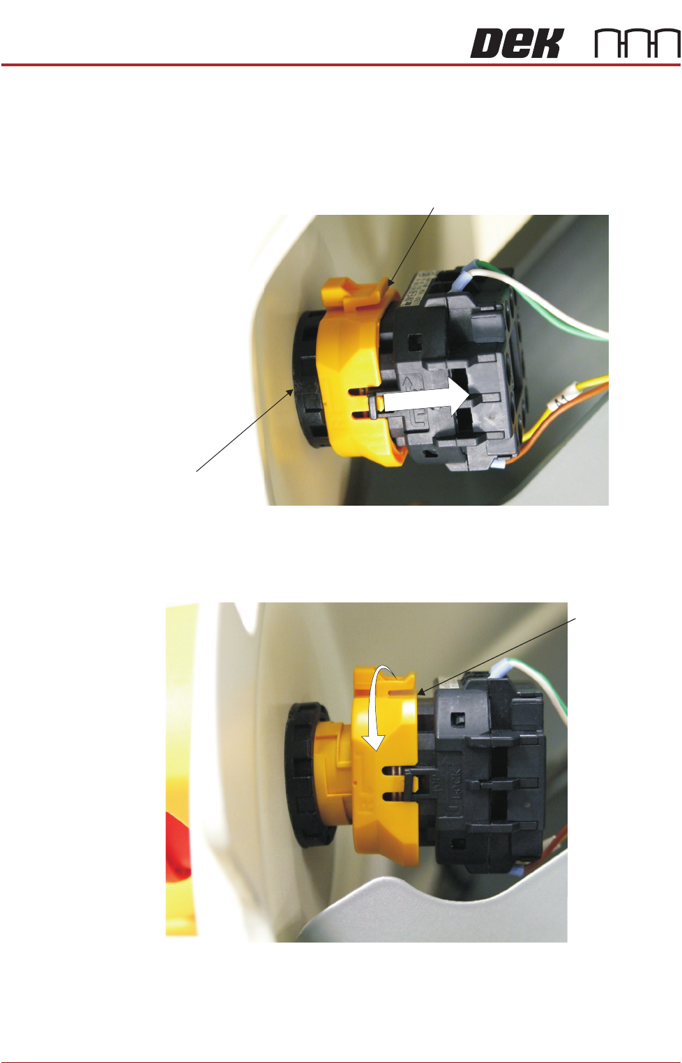
3. To remove the left hand front corner panel only, the front EMO switch must
be disconnected. To disconnect the EMO carry out the following:
a. Locate the yellow locking collar at the rear of the switch.
b. Slide the collar rearwards towards the switch contact assembly against
spring pressure.
4. Viewed from the rear of the switch, rotate the locking collar anticlockwise
to release the contact assembly from the switch body.
Locking Collar
EMO Switch
View From Inside Front Left Hand Corner Panel
Locking Collar
View From Inside Front Left Hand Corner Panel
COVERS
PRINTER COVERS
Chapter Issue 4, Nov 14 Installation Manual 2.13
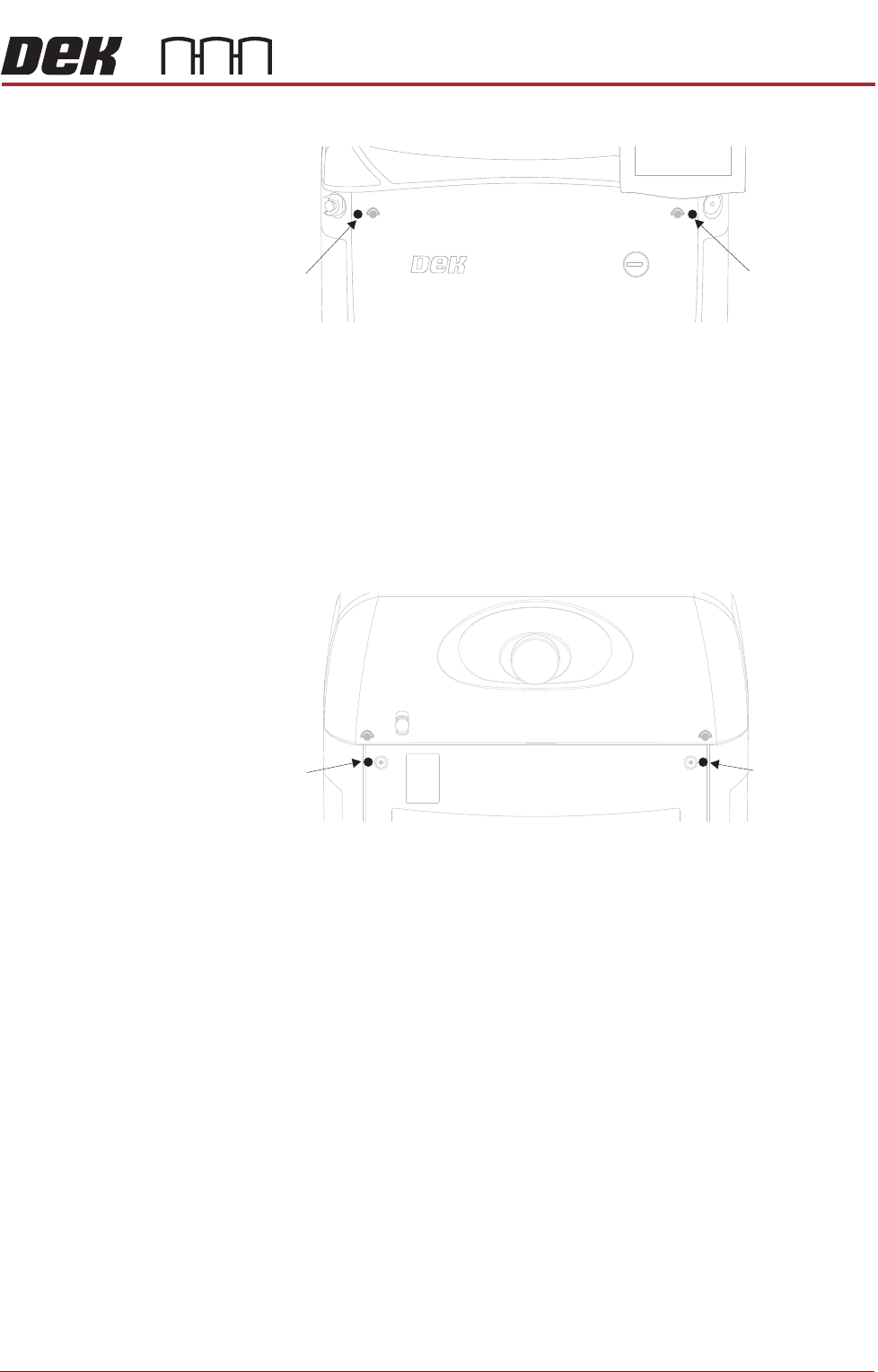
5. Release the quarter-turn fastener that secures the corner panel.
6. Lift the corner panel upwards to disconnect the panel from the side panel
and the guide pins that locate the panel to the machine frame.
NOTE
Failure to assemble the front EMO switch correctly results in the EMO
circuit remaining active preventing the machine from being powered up.
Rear Corner
Panels
To remove the rear corner panels, carry out the following:
1. Remove the corresponding upper side panel (as detailed previously).
2. Release the quarter-turn fastener that secures the corner panel.
3. Lift the corner panel upwards to disconnect the panel from the side panel
and the guide pins that locate the panel to the machine frame.
4. Repeat Steps 1 to 3 for the other corner panel, if required.
Side Panels To remove the side panels, carry out the following:
1. Remove both corresponding corner panels (as detailed previously).
Front Corner
Panel Quarter-
Turn Fastener
Front Corner
Panel Quarter-
Turn Fastener
Rear Corner
Panel Quarter-
Turn Fastener
Rear Corner
Panel Quarter-
Turn Fastener