196396 Iss 2 Nov 2015 - Semi Appendix Manual.pdf - 第27页
COVERS PRINTER COVERS Chapter Issue 4, Nov 14 Installation Manual 2.13 5. Release the quarter -turn fastener tha t secures the corner pa nel. 6. Lift the corner panel upward s to disconnect the panel from the side panel …
COVERS
PRINTER COVERS
2.12 Installation Manual Chapter Issue 4, Nov 14
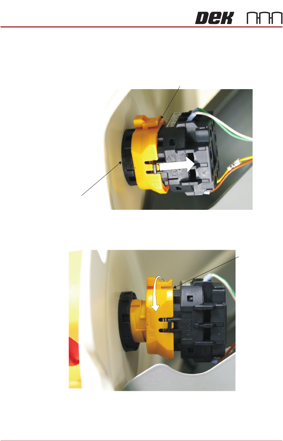
3. To remove the left hand front corner panel only, the front EMO switch must
be disconnected. To disconnect the EMO carry out the following:
a. Locate the yellow locking collar at the rear of the switch.
b. Slide the collar rearwards towards the switch contact assembly against
spring pressure.
4. Viewed from the rear of the switch, rotate the locking collar anticlockwise
to release the contact assembly from the switch body.
Locking Collar
EMO Switch
View From Inside Front Left Hand Corner Panel
Locking Collar
View From Inside Front Left Hand Corner Panel
COVERS
PRINTER COVERS
Chapter Issue 4, Nov 14 Installation Manual 2.13
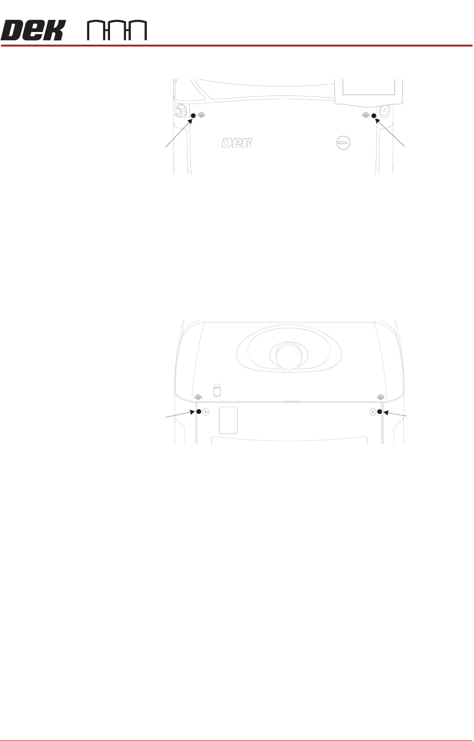
5. Release the quarter-turn fastener that secures the corner panel.
6. Lift the corner panel upwards to disconnect the panel from the side panel
and the guide pins that locate the panel to the machine frame.
NOTE
Failure to assemble the front EMO switch correctly results in the EMO
circuit remaining active preventing the machine from being powered up.
Rear Corner
Panels
To remove the rear corner panels, carry out the following:
1. Remove the corresponding upper side panel (as detailed previously).
2. Release the quarter-turn fastener that secures the corner panel.
3. Lift the corner panel upwards to disconnect the panel from the side panel
and the guide pins that locate the panel to the machine frame.
4. Repeat Steps 1 to 3 for the other corner panel, if required.
Side Panels To remove the side panels, carry out the following:
1. Remove both corresponding corner panels (as detailed previously).
Front Corner
Panel Quarter-
Turn Fastener
Front Corner
Panel Quarter-
Turn Fastener
Rear Corner
Panel Quarter-
Turn Fastener
Rear Corner
Panel Quarter-
Turn Fastener
SERVICES REQUIRED
EXTERNAL SERVICES
3.2 Installation Manual Chapter Issue 4, Nov 14
Pneumatic Supply The machine requires a pneumatic supply of clean, non lubricated air which
should maintain a minimum pressure 5 Bar and a maximum of 8 Bar.
The air should be to ISO 8573.1 standard, quality class 2.3.3, where:
• 2 dirt = 1 micron
• 3 water = -20°C pressure dewpoint
• 3 oil = 1mg/m3
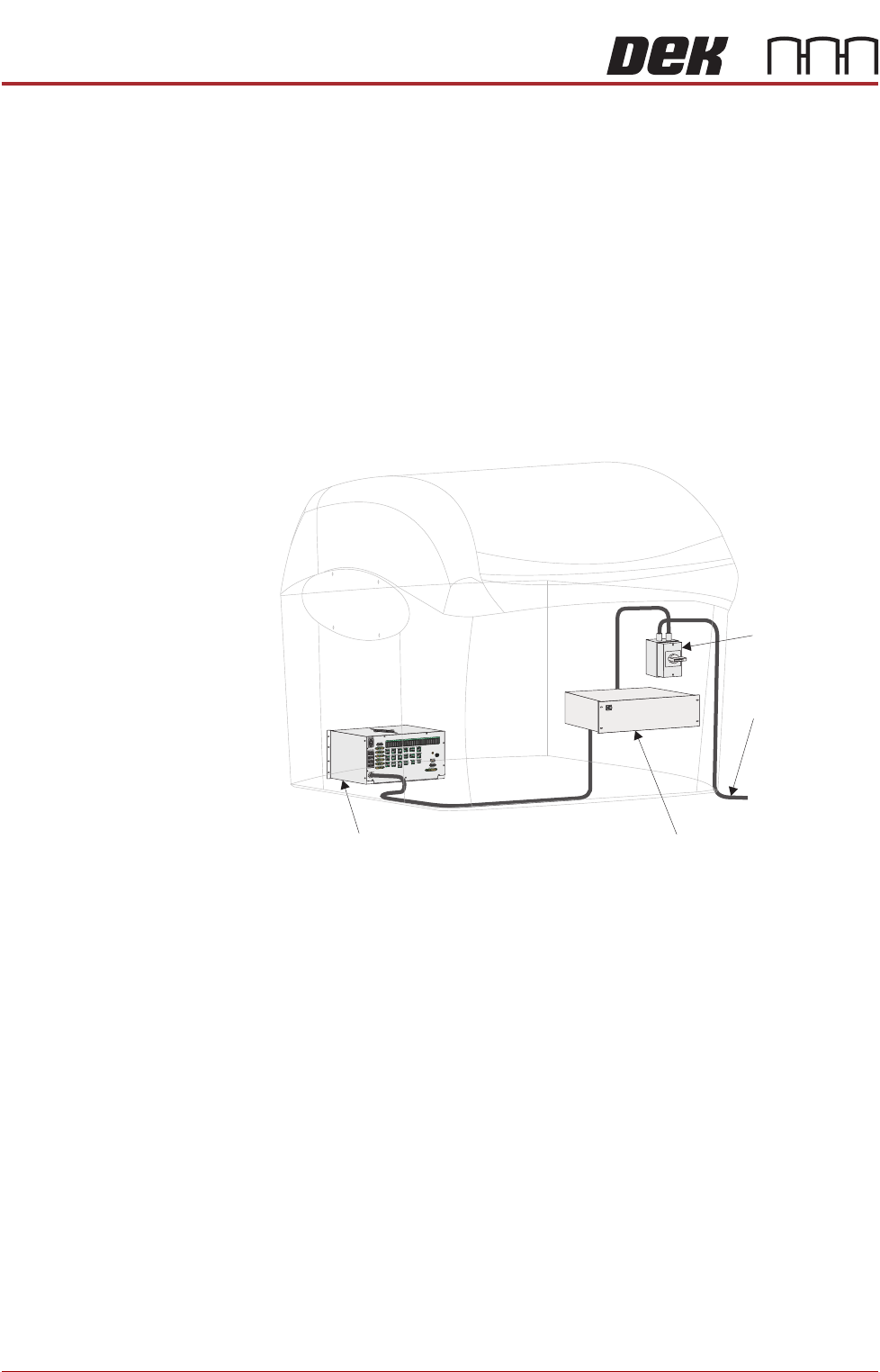
Electrical Supply The factory mains supply for the machine is routed through the front panel
mounted mains isolator switch to the M39 EMO enclosure. If both EMO push
button switches are de-activated and the Start button has been pressed mains
voltage is applied to the M37 power supply enclosure. From the enclosure
various low voltages are distributed throughout the machine.
Figure 3-1 Mains Electrical Supply
The machine operates on 100V to 240V + 10% 50/60Hz single phase ac mains,
current rating 10A or 2.4Kw.
NOTE
The voltage selector of the VF35i vacuum filtration unit needs to be set to the
factory mains supply. This is carried out in the Machine Preparation Chapter
later in this manual.
ASM recommends a power supply capacity of 2.4KVA or greater.
From Factory
Mains Supply
Mains Isolator
Switch
M37 Power Supply Enclosure
M39 EMO Enclosure