196396 Iss 2 Nov 2015 - Semi Appendix Manual.pdf - 第29页
SERVIC ES REQU IRED EXTERNAL SERVICES Chapter Issue 4, Nov 14 Installation Manual 3.3 ASM requires addit ional machine supply protect ion with the fitment of an external double pole circui t breaker conforming to nat ion…
SERVICES REQUIRED
EXTERNAL SERVICES
3.2 Installation Manual Chapter Issue 4, Nov 14
Pneumatic Supply The machine requires a pneumatic supply of clean, non lubricated air which
should maintain a minimum pressure 5 Bar and a maximum of 8 Bar.
The air should be to ISO 8573.1 standard, quality class 2.3.3, where:
• 2 dirt = 1 micron
• 3 water = -20°C pressure dewpoint
• 3 oil = 1mg/m3
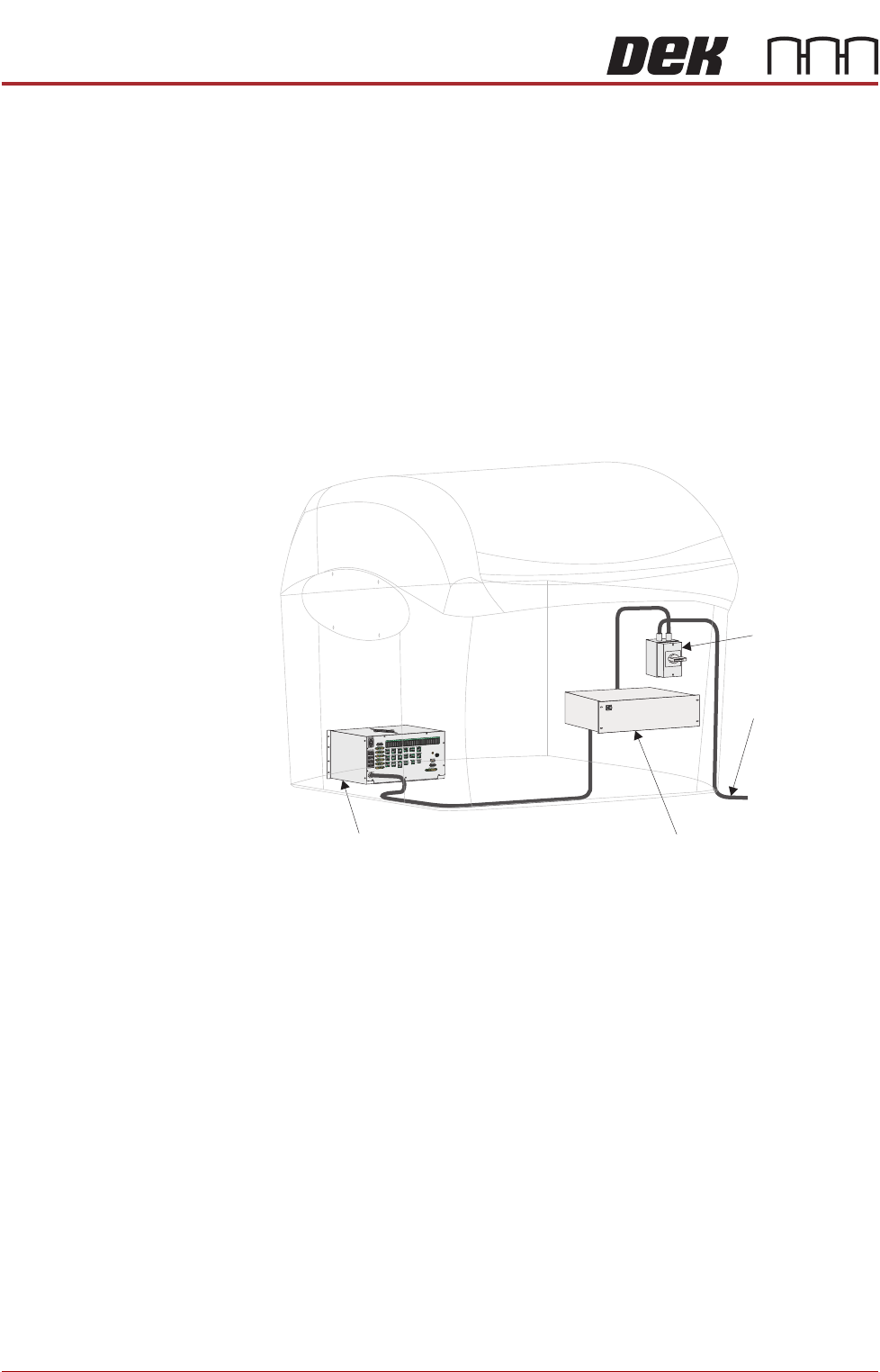
Electrical Supply The factory mains supply for the machine is routed through the front panel
mounted mains isolator switch to the M39 EMO enclosure. If both EMO push
button switches are de-activated and the Start button has been pressed mains
voltage is applied to the M37 power supply enclosure. From the enclosure
various low voltages are distributed throughout the machine.
Figure 3-1 Mains Electrical Supply
The machine operates on 100V to 240V + 10% 50/60Hz single phase ac mains,
current rating 10A or 2.4Kw.
NOTE
The voltage selector of the VF35i vacuum filtration unit needs to be set to the
factory mains supply. This is carried out in the Machine Preparation Chapter
later in this manual.
ASM recommends a power supply capacity of 2.4KVA or greater.
From Factory
Mains Supply
Mains Isolator
Switch
M37 Power Supply Enclosure
M39 EMO Enclosure
SERVICES REQUIRED
EXTERNAL SERVICES
Chapter Issue 4, Nov 14 Installation Manual 3.3
ASM requires additional machine supply protection with the fitment of an
external double pole circuit breaker conforming to national, federal or local
legislation. ASM recommends that the external circuit breaker is fitted near the
DEK printer and within easy reach of the operator. Use the following table to
ensure the recommended circuit breaker is used:
NOTE
An over current circuit breaker protects the machines internal wiring and
components from overheating or catching fire during fault conditions. Under no
circumstances must a circuit breaker of value greater than 25 Amps be fitted.
Equipment If the equipment is used in a manner not specified by the manufacturer, the
protection provided by the equipment may be impaired.
This equipment should be used in accordance with the operating instructions.
ASM absolves itself of all responsibility if the machine is not used within its
operating envelope or for it’s intended purpose.
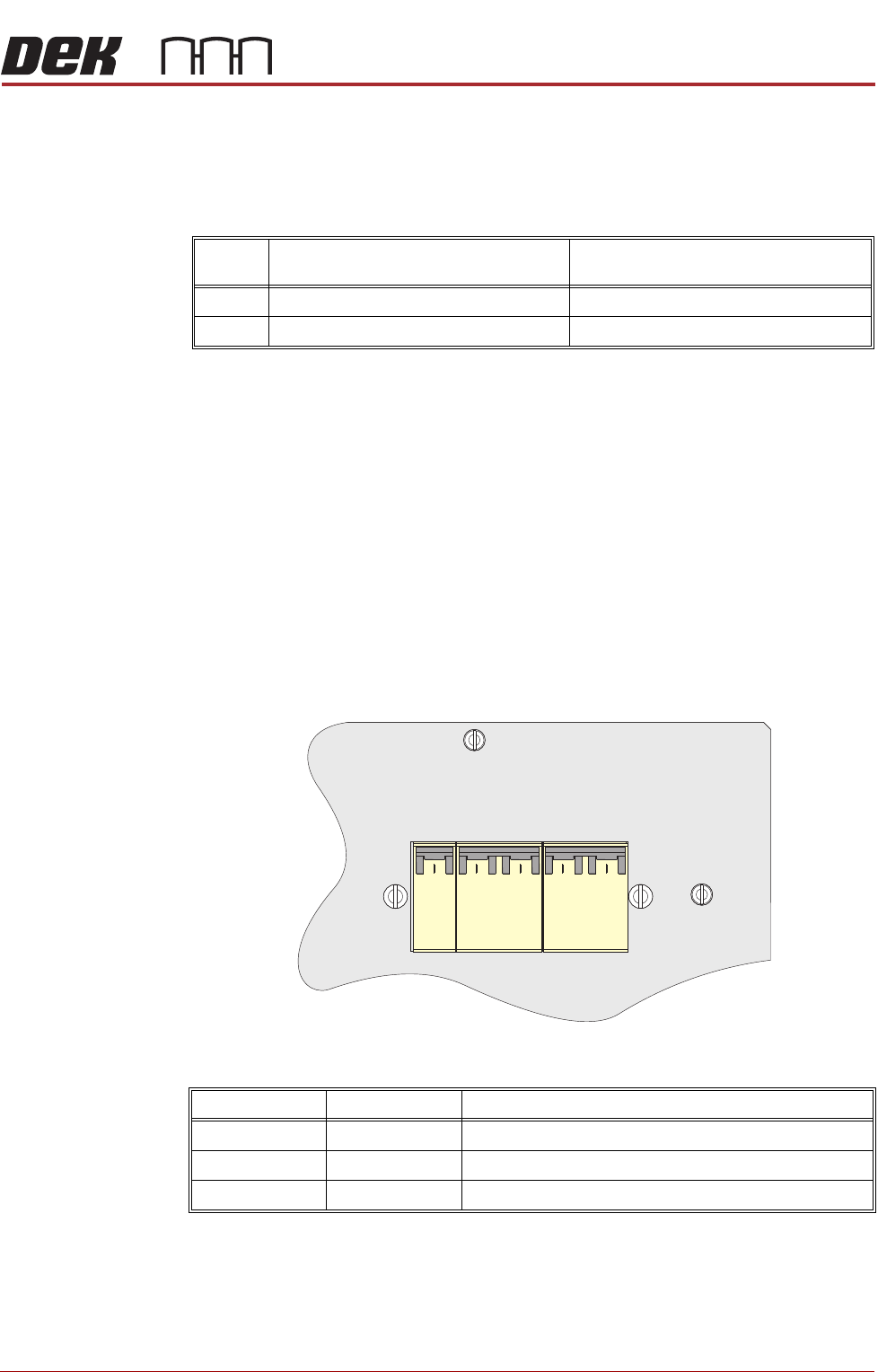
Circuit Breakers The M37 Power Supply Enclosure has circuit breakers on the front and rear
panels of the enclosure.
Front Panel Circuit
Breakers
Voltage Value of Wall Mounted Circuit Breaker
(without Internal Vacuum Unit)
Value of Wall Mounted Circuit Breaker
(with Internal Vacuum Unit)
115V 10 Amp 25 Amp
230V 4/6 Amp 13/16 Amp
CCT Breaker Current Rating CCT Breaker Function
CB32 10A +42V or +48V Servo DC Supply
CB33 10A Mains Supply PC and Monitor
CB34 16A Mains Supply Internal Vac Pump
CB32
CB33
CB34
10A
Type C
10A
Type C
16A
Type C
Part View of Front Panel
MACHINE PREPARATION
PRE POWER UP CHECKS
Chapter Issue 4, Nov 14 Installation Manual 16.45
PRE POWER UP CHECKS
Having removed the transit brackets and assembled the machine, prepare to
install the machine, as follows:
Electrical Test Before the machine is connected to the factory electrical supply, the following
electrical tests must be performed:
1. Ensure the mains isolator switch is in the OFF position.
2. Remove the front cover of the machine to gain access to the mains isolator
switch.
3. Remove the front cover of the mains isolator switch.
4. Loosen the two blue coloured terminal cover securing screws and remove
the cover.
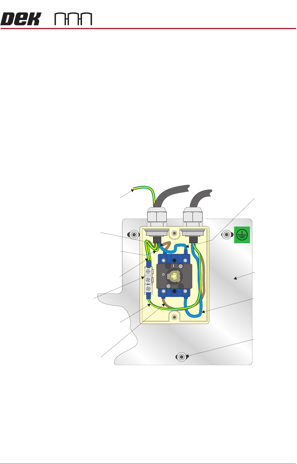
5. Perform a visual inspection of the mains isolator switch ensuring the follow-
ing:
a.The earth input and earth output cables are connected to the earth tag.
b.The live input is connected to the top of the isolator switch on the left hand
side.
c.The live output is connected to the bottom of the isolator switch on the left
hand side.
d.The neutral input is connected to the top of the isolator switch on the right
hand side.
e.The neutral output is connected to the bottom of the isolator switch on the
right hand side.
OFF
ON
L1 L2
T1 T2
Isolator Mount
Live (Brown)
Input
Earth (Green/Yellow)
Input (Top Wire)
Earth (Green/Yellow)
Output
Earth Tag
Live (Brown)
Output
Neutral (Blue)
Input
Isolator Mount
Securing Screw
(in 3 positions)
Neutral (Blue)
Output
Earth (Green/Yellow)
to machine’s earth point
Earth (Green/Yellow)
to machine’s earth
point