196396 Iss 2 Nov 2015 - Semi Appendix Manual.pdf - 第31页
MACHINE PREPAR ATION PRE POWE R UP CHECKS 16.46 Installation Manual Chapter Issue 4, N ov 14 6. Ensure that al l seven cables are secure and no bare wires are showing. 7. Connect t he two probes of a digita l volt meter …
MACHINE PREPARATION
PRE POWER UP CHECKS
Chapter Issue 4, Nov 14 Installation Manual 16.45
PRE POWER UP CHECKS
Having removed the transit brackets and assembled the machine, prepare to
install the machine, as follows:
Electrical Test Before the machine is connected to the factory electrical supply, the following
electrical tests must be performed:
1. Ensure the mains isolator switch is in the OFF position.
2. Remove the front cover of the machine to gain access to the mains isolator
switch.
3. Remove the front cover of the mains isolator switch.
4. Loosen the two blue coloured terminal cover securing screws and remove
the cover.
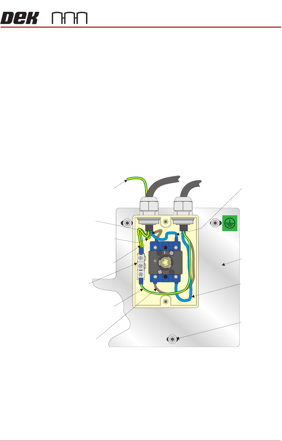
5. Perform a visual inspection of the mains isolator switch ensuring the follow-
ing:
a.The earth input and earth output cables are connected to the earth tag.
b.The live input is connected to the top of the isolator switch on the left hand
side.
c.The live output is connected to the bottom of the isolator switch on the left
hand side.
d.The neutral input is connected to the top of the isolator switch on the right
hand side.
e.The neutral output is connected to the bottom of the isolator switch on the
right hand side.
OFF
ON
L1 L2
T1 T2
Isolator Mount
Live (Brown)
Input
Earth (Green/Yellow)
Input (Top Wire)
Earth (Green/Yellow)
Output
Earth Tag
Live (Brown)
Output
Neutral (Blue)
Input
Isolator Mount
Securing Screw
(in 3 positions)
Neutral (Blue)
Output
Earth (Green/Yellow)
to machine’s earth point
Earth (Green/Yellow)
to machine’s earth
point

MACHINE PREPARATION
PRE POWER UP CHECKS
16.46 Installation Manual Chapter Issue 4, Nov 14
6. Ensure that all seven cables are secure and no bare wires are showing.
7. Connect the two probes of a digital volt meter (DVM) together and ensure
that the DVM is reading 0Ω.
8. Measure the resistance between the earth tag and all three isolator mount
securing screws ensuring that all measurements are less than 0.5Ω.
9. Remove the rear cover of the machine.
10. Measure the resistance between the following points ensuring that all
measurements are less than 0.5Ω:
a.PC earth stud and a securing screw that secures the PC to the machine
frame.
b.M36 earth stud and a securing screw that secures the M36 to the machine
frame.
c.M37 earth stud and a securing screw that secures the M37 to the machine
frame.
d.M39 earth stud and a securing screw that secures the M39 to the machine
frame.
e.M27 earth stud and a securing screw that secures the M27 to the machine
frame.
11. Refit the rear cover.
12. Refit the terminal cover.
13. Refit the mains isolator cover.
14. Refit the front cover.
POWER UP SEQUENCE
MACHINE POWER UP SEQUENCE
Chapter Issue 4, Nov 14 Installation Manual 5.11
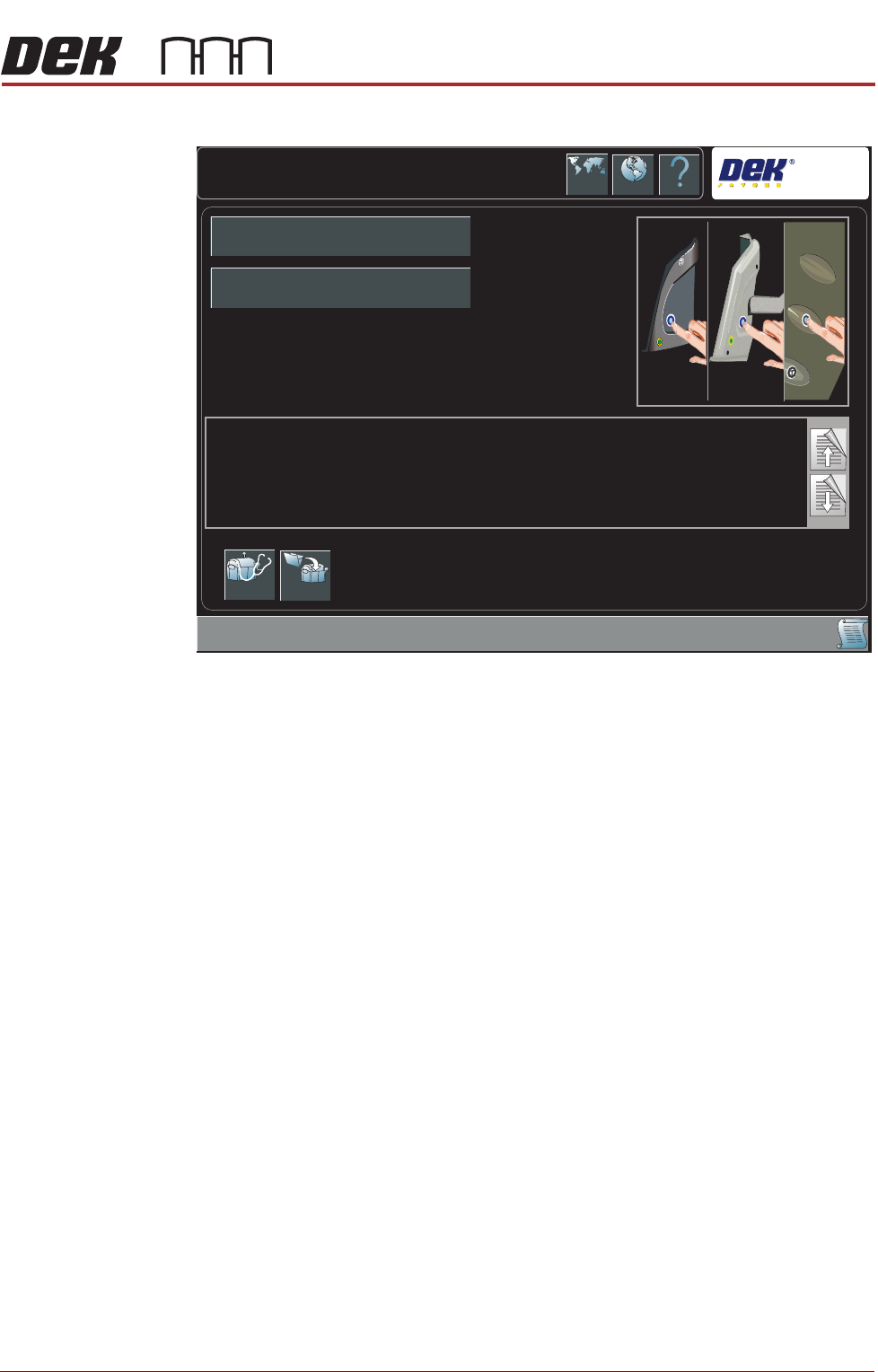
i. During the machine initialisation, the following window is displayed:
j. Press the System button.
Printhead Cover
Loop & EMO
Operation
3. Carry out the following procedure for printhead cover loop & EMO operation
check:
a. Press the EMO button.
b. Reset the EMO by turning the button clockwise until it unlatches.
c. Press the Start button to restore electrical and pnuematic power to the
machine.
d. Press the System button when prompted.
e. Open the front printhead cover. The Machine Operation Suspended -
Cover Open window is displayed.
f. Close the front printhead cover.
g. Press the System button when prompted.
System Initialisation
DEK
Press the System button on the outer cover, to initialise the machine,
OR...
Select Diagnostics - to enter the machine’s diagnostic functions,
OR...
If the current product file needs to be changed, select Load Product to load another product file.
Diagnostics Load
Product Name
Product ID