196396 Iss 2 Nov 2015 - Semi Appendix Manual.pdf - 第36页
EMERGENCY MACHINE OFF (EMO) MODULE OVERVIEW 5.2 Technical Reference Manual Chapter Issue 2, Nov 14 WARNING LETHAL VOLTAGE. DANGEROUS VOLT AGES EXIST IN THIS EQUIPMENT. ENSURE ALL ELECTRONIC COVERS AN D MAIN MACHINE C OVE…
EMERGENCY MACHINE OFF (EMO) MODULE
OVERVIEW
Chapter Issue 2, Nov 14 Technical Reference Manual 5.1
CHAPTER 5 EMERGENCY MACHINE OFF (EMO) MODULE
OVERVIEW
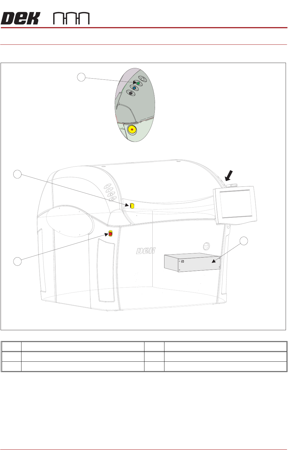
Item Description Item Description
1 M39 Emergency Machine Off Enclosure 3 Rear Emergency Machine Off Switch
2 Front Emergency Machine Off Switch 4 Start Button
A
View on Arrow A
2
3
4
1

EMERGENCY MACHINE OFF (EMO) MODULE
OVERVIEW
5.2 Technical Reference Manual Chapter Issue 2, Nov 14
WARNING
LETHAL VOLTAGE. DANGEROUS VOLTAGES EXIST IN THIS EQUIPMENT.
ENSURE ALL ELECTRONIC COVERS AND MAIN MACHINE COVERS ARE FITTED
BEFORE OPERATING THIS EQUIPMENT.
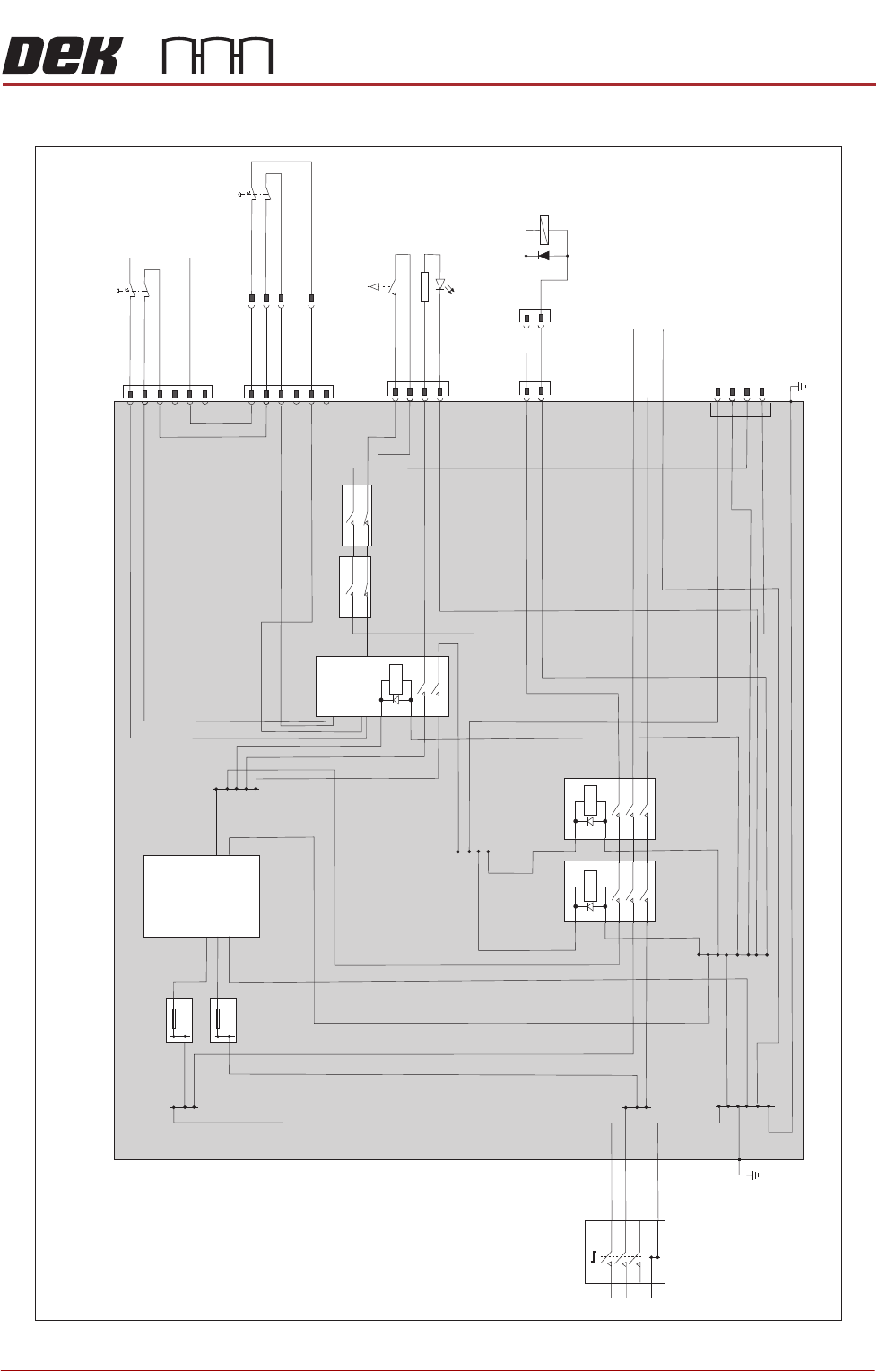
Mains input power (115V to 230V) to the machine is routed to the mains isolator
switch at the front of the machine. From the mains isolator it is fed to the M39
emergency machine off enclosure, through one of the cable glands at the rear
panel, to the three terminal blocks TB1 (live), TB2 (neutral) and TB3 (earth).
From the terminal blocks mains power is supplied to the EMO Safe Power
Supply Unit (EMO PSU) and to M37 power supply crate via the closed contacts
of contactors CON1 and CON2.
The EMO PSU supplies +24V dc to terminal block TB 4. From TB 4 the +24V
dc is distributed to the E-Stop relay RL 1 and the pneumatic dump valve
16SOL37 through the closed contacts of CON1 and CON2.
The front and rear EMO push button switches are connected in series across
relay RL1. If either switch is operated the mains power supply to the M37 power
supply crate is immediately removed. The pneumatic air pressure supply to the
machine is also removed and any remaining pneumatic pressure within the
machine is vented safely to atmosphere.
The front panel connector (M39SK5) is provided for maintenance purposes to
apply a +24V dc supply to the EMO enclosure for electrical testing.
NOTE
Following a service visit that involves any disturbance of components in the
mains voltage circuit an electrical test as detailed in the Pre Power section of
the Transportation chapter must be undertaken. Before testing ensure that the
machine is isolated from the factory supply and that any external equipment (ie
upline and downline conveyors) are disconnected.
EMERGENCY MACHINE OFF (EMO) MODULE
ELECTRICAL SCHEMATIC
Chapter Issue 2, Nov 14 Technical Reference Manual 5.3
ELECTRICAL SCHEMATIC
N
N
E
E
Mains
Isolator
TB1
TB2
TB3
TB8
L
L
TB4
TB5
TB7
8A
EMO Safe PSU
M39 Emergency
Machine
Off Enclosure
PSU 1
L
+24V
0V
N
E
TB6
8A
CON1
CON2
RL1
E-Stop
Relay
M39PL1
Front EMO
8SE5
1
2
3
4
5
6
M39P
L3
M39SK5
M39PL4
16SK37
Start Button
14SW4
Pneumatic
Dump
16SOL37
1
1
1
1
+ve
-ve
2
2
2
2
3
3
4
4
Front Panel
M39PL2
1
2
3
4
5
6
E
To M37 Power
Supply Crate
For Electrica
l
Testing
8SK/PL64
Rear EMO
8SE6
1
2
3
5