196396 Iss 2 Nov 2015 - Semi Appendix Manual.pdf - 第38页
EMERGENCY MACHINE OFF (EMO) MODULE M39 EMERGENCY MACHINE OFF ENCLOSURE 5.4 Technical Reference Manual Chapter Issue 2, Nov 14 M39 EMERGENCY MACHINE OFF ENCLOSURE Figure 5-1 M39 Emergency Machine Off Enclosu re - Plan Vie…
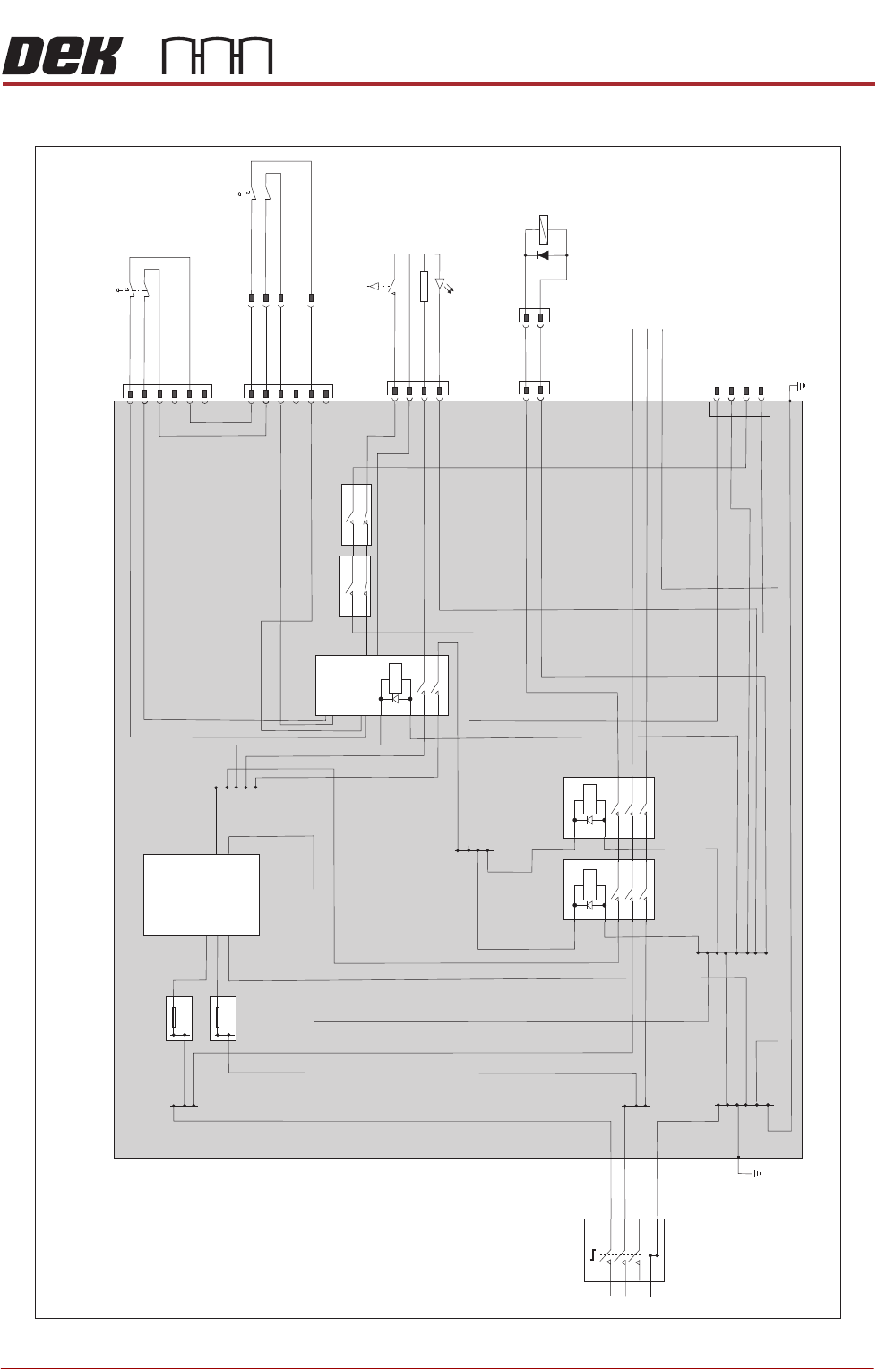
EMERGENCY MACHINE OFF (EMO) MODULE
ELECTRICAL SCHEMATIC
Chapter Issue 2, Nov 14 Technical Reference Manual 5.3
ELECTRICAL SCHEMATIC
N
N
E
E
Mains
Isolator
TB1
TB2
TB3
TB8
L
L
TB4
TB5
TB7
8A
EMO Safe PSU
M39 Emergency
Machine
Off Enclosure
PSU 1
L
+24V
0V
N
E
TB6
8A
CON1
CON2
RL1
E-Stop
Relay
M39PL1
Front EMO
8SE5
1
2
3
4
5
6
M39P
L3
M39SK5
M39PL4
16SK37
Start Button
14SW4
Pneumatic
Dump
16SOL37
1
1
1
1
+ve
-ve
2
2
2
2
3
3
4
4
Front Panel
M39PL2
1
2
3
4
5
6
E
To M37 Power
Supply Crate
For Electrica
l
Testing
8SK/PL64
Rear EMO
8SE6
1
2
3
5
EMERGENCY MACHINE OFF (EMO) MODULE
M39 EMERGENCY MACHINE OFF ENCLOSURE
5.4 Technical Reference Manual Chapter Issue 2, Nov 14
M39 EMERGENCY MACHINE OFF ENCLOSURE
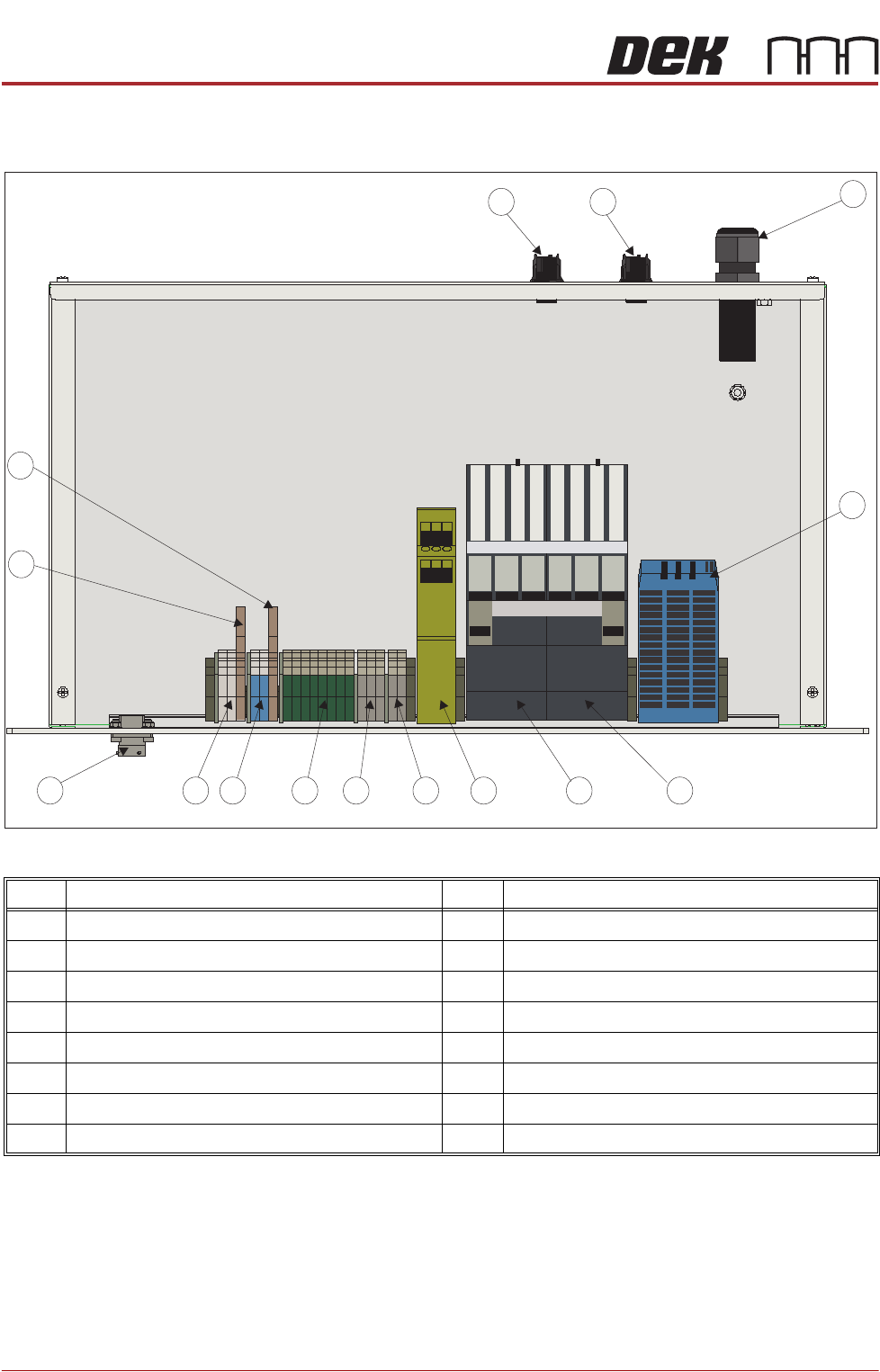
Figure 5-1 M39 Emergency Machine Off Enclosure - Plan View
Item Description Item Description
1 Mains Power Input & Output Glands 9 Terminal Block TB2
2 EMO Safe Power Supply Unit PSU 1 10 Terminal Block TB1
3 Contactor CON1 11 Socket M39SK05
4 Contactor CON2 12 Terminal Block TB6
5 E-Stop Relay RL1 13 Terminal Block TB7
6 Terminal Block TB5 14 Sockets M39SK2 & 4
7 Terminal Block TB4 15 Sockets M39SK1 & 3
8 Terminal Block TB3
1
2
3456789
1011
12
13
14
15

EMERGENCY MACHINE OFF (EMO) MODULE
M39 EMERGENCY MACHINE OFF ENCLOSURE
Chapter Issue 2, Nov 14 Technical Reference Manual 5.5
Emergency
Machine Off
The emergency machine off circuit comprises the following:
• The E Stop Relay
•Start Switch
• Front EMO Switch
• Rear EMO Switch
• Pneumatic Dump Valve
• EMO Safe PSU
• Contactors CON1 and CON2
Powering Up When the mains isolator is switched on mains input voltage is supplied to the
M39 enclosure. The input voltage is distributed within the enclosure via Terminal
Blocks TB1, TB2 and TB3. Initially the input voltage is applied to the open
contacts of Contactors CON1 and CON2. The input voltage is also distributed
via fused Terminal Blocks TB6 and TB7 to the EMO Safe PSU. The PSU
produces a +24V dc which is distributed via Terminal Block TB4.
When the Start Button is pressed, the supply to the E-Stop relay is complete
and the relay energises. The relay contacts close supplying 24V dc via Terminal
Block TB5 to the solenoids of CON1 and CON2. The contactors are energised
and the closed contacts complete the circuit to the M37 enclosure allowing the
machine is power up.
An additional set of contactor contacts supply 24V dc to the pneumatic dump
valve allowing the factory pneumatic supply to be applied to the machine.
EMO Operation If either of EMO push button switches are operated the E-Stop relay is de-
energised causing the 24V dc supply to the solenoids of CON1 and CON2 to
be broken. Contacts of CON1 and CON2 are opened, breaking the mains input
voltage to the M37 enclosure, immediately removing electrical power from the
machine. Also the 24V dc supply to the pneumatic dump valve is removed de-
energising the valve. The factory pneumatic supply is removed from the
machine and the any residual machine pneumatic pressure is vented safely to
atmosphere.