VACUUM SENSOR EbD.pdf - 第4页
MPU No: 602422*1 ISSUE No: 01 DOC No: 225877 ISSUE No: 01 SHEET 4 OF 8 Machine Performance Upgrade d. Plug loom into Sensor and Route the cable across to the trunking on the left and run the loom to the rear of the machi…
MPU No: 602422*1
ISSUE No: 01
DOC No: 225877
ISSUE No: 01
SHEET 3 OF 8 Machine Performance Upgrade
DETAILS OF CHANGE
1. VACUUM SENSOR FIT and SET-UP
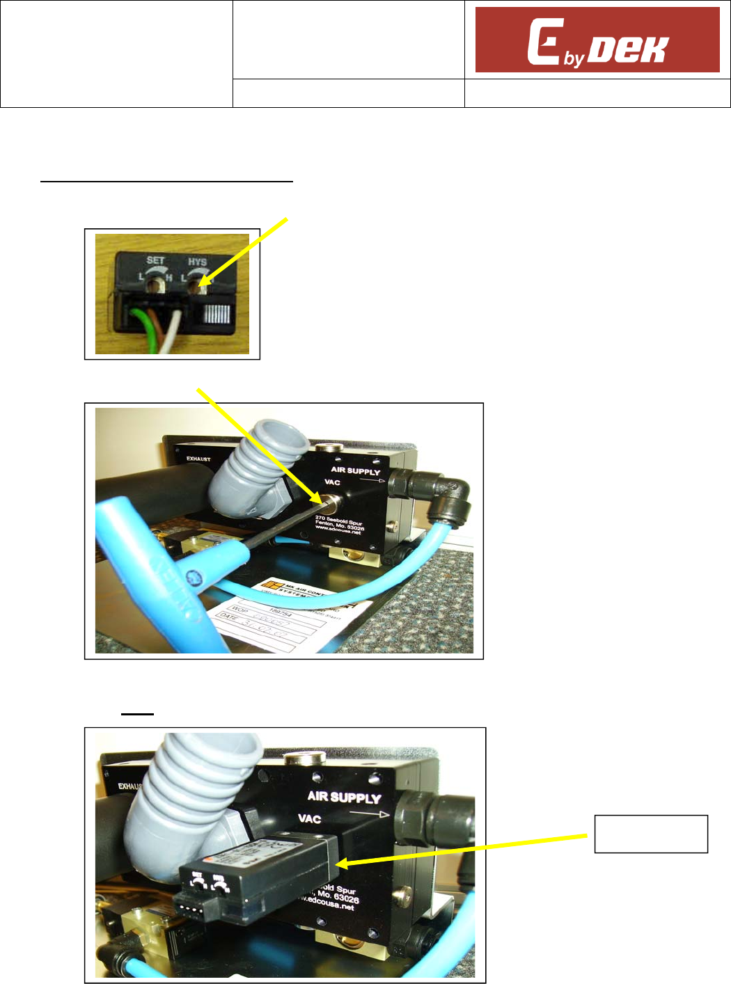
a. Turn the hysteresis trimmer (HYS) on the vacuum sensor Anti-Clockwise to minimum (L).
b. Remove the (4mm) metal blanking plug screwed into the rear of the Venturi vacuum unit.
c. Fit the vacuum sensor (188981, part of vac sense loom 185060), using a spanner on the metal
base, NOT the plastic body. Use thread sealant sparingly on the sensor threads.
Metal base
MPU No: 602422*1
ISSUE No: 01
DOC No: 225877
ISSUE No: 01
SHEET 4 OF 8 Machine Performance Upgrade
d. Plug loom into Sensor and Route the cable across to the trunking on the left and run the loom to
the rear of the machine to node board 2.
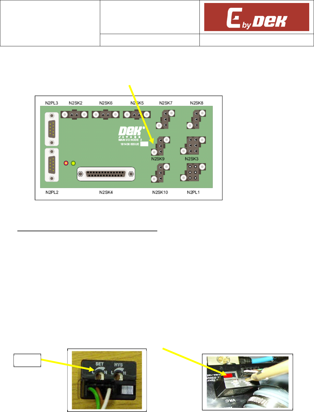
e. Connect the loom N2PL9 to N2SK9 of the signal breakout loom situated on the rear left.
f. Reconnect both Air and Power supplies.
2. VACUUM SENSE TESTING (V09 SOFTWARE)
NOTE
This test is to be carried out together with the Venturi vacuum test.
a. In Machine Software select - Maintenance – Machine set up – Tooling Hardware.
b. Select Vacuum and Accept.
c. In Diagnostics, toggle the Vac Tooling to confirm correct operation.
d. Block the end of the vacuum pipe with the Alignment test board and activate the vacuum unit.
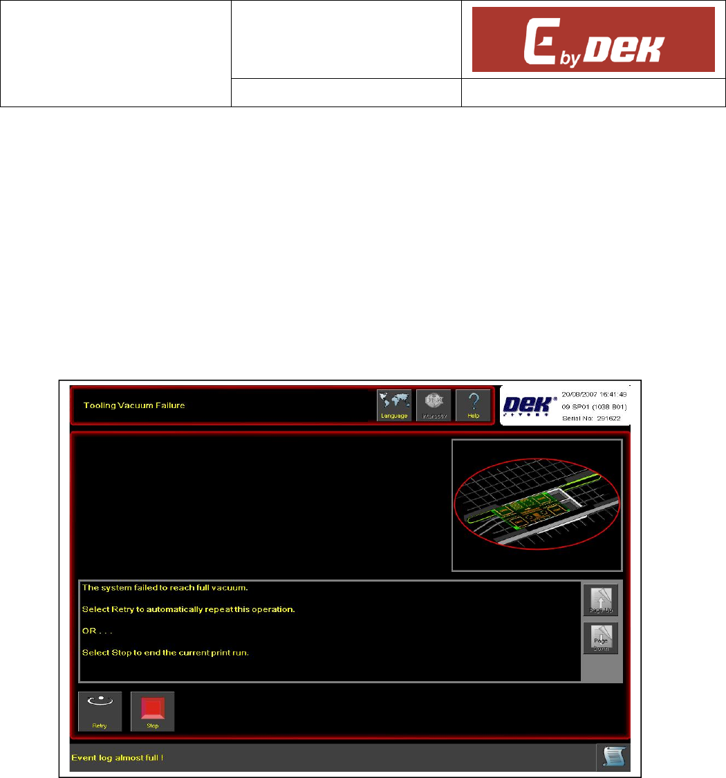
e. Turn the pressure-setting trimmer (SET) clockwise to its limit, and then turn anti-clockwise until
the switch changes from OFF to ON (LED indicator lights).
SET
MPU No: 602422*1
ISSUE No: 01
DOC No: 225877
ISSUE No: 01
SHEET 5 OF 8 Machine Performance Upgrade
f. Move the test board to create a small leak and ensure the sensor switches and the output
changes (NODE2 GROUP 0 ) to detect the leak. This is to replicate displaced or poorly located
substrates on the tooling.
g. Repeat this test 5 times once you have set the sensor.
h. If switch “chattering” occurs during operation increase the hysteresis setting to further separate
the OFF and ON settings.
i. Initialise the machine and load a screen.
j. Cycle the machine and deliberately cause a leak by not covering the vacuum tube. The
machine will stop and display an error message on the screen.
k. Cover the end of the pipe and press retry, the machine should carry on with the cycle.