西门子SIPLACE S25 HM-设备性能参数_EN - 第12页
10 Description On SIPLACE S-25 HM the in-line conveyor system guarantees a quick adjustment to new PCB widths. The ch ange is made either at the station computer u sing the menu function or from the line computer v ia th…
9
Description
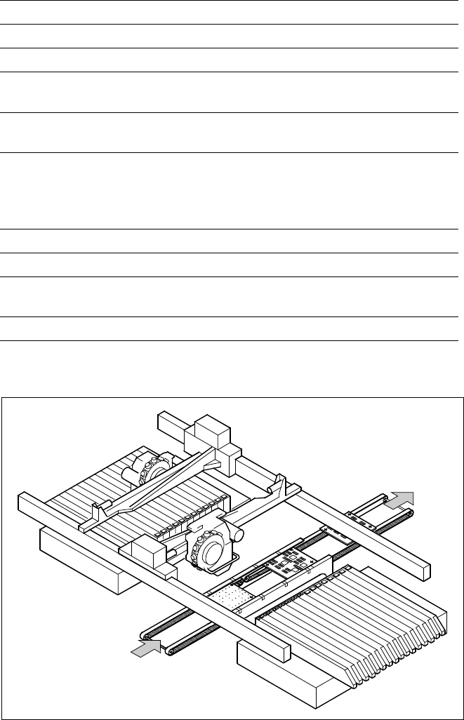
A nozzle changer corresponding to
the Collect & Place Head in use
can be installed to the left of the
PCB conveyor with no loss of
feeder capacity. It will change the
nozzle set-up of the placement
head quickly and reliably for the
specific nozzle configuration valid
to a job. Damaged or faulty nozzles
can be exchanged via the menu
function on the station computer.
Placement Heads:
Nozzle Changer
Technical Data
12-Nozzle Collect & Place Head
Type of nozzle All standard nozzles of nozzle series 7xx/9xx
(special nozzles must be tested individually)
Capacity 8 magazines, each with 12 nozzles of one
nozzle type
Nozzle changing times About 2 s per nozzle
6-Nozzle Collect & Place Head
Type of nozzle All standard nozzles of nozzle series 7xx and 8xx
(special nozzles must be tested individually)
Capacity 5 magazines, each with 6 nozzles of one nozzle
series
Nozzle changing times About 2 s per nozzle
Position of Nozzle Changers
Component
Feeders for
Collect & Place
Heads
PCB
Nozzle Changer for 12-Nozzle Collect & Place Head
(7 Magazines, each with 12 Nozzles, Option)
and/or
Nozzle Changer for 6-Nozzle Collect & Place Head
(5 Magazines, each with 6 Nozzles, Option)
Component
Feeders for
Collect & Place
Heads
10
Description
On SIPLACE S-25 HM the in-line
conveyor system guarantees a
quick adjustment to new PCB
widths. The change is made either
at the station computer using the
menu function or from the line
computer via the automatic width
adjustment unit.
Ceramic substrates can be also
transported and, if necessary, fas-
tened in place with the optional
ceramic substrate centering unit.
The single conveyor system is
standard on SIPLACE placement
systems.
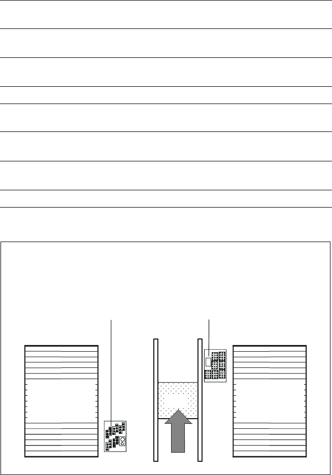
PCB Conveyor:
Single Conveyor
Technical Data
PCB dimensions See table on page 3
PCB thickness 0.5 to 4.5 mm
Max. PCB weight 3 kg
Max. PCB warpage Top: 4.5 mm - PCB thickness
Bottom: 0.5 mm + PCB thickness
Free space on PCB bottom side Standard: 25 mm,
Option: max. 40 mm
PCB conveyor height
830
± 15 mm (Standard)
900
± 15 mm (Option)
930
± 15 mm (Option)
950
± 15 mm (Option) SMEMA
Fixed conveyor edge Right (standard), left (option)
Type of interface Siemens (standard); SMEMA (option)
Component-free PCB
handling edge 3 mm
PCB loading time 2.5 s
PCB Conveyor
PCB
Transport Direction
11
Description
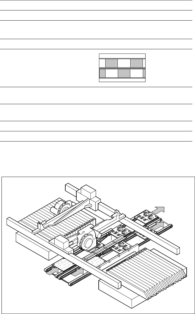
Thanks to reduced non-productive
times the dual PCB conveyor can
substantially increase the through-
put, depending on the program. It
makes it possible to transport two
PCBs through the machine.
In the asynchronous mode of
transport a PCB is moved into the
machine in “slack time” while an-
other of the same PCB is being
populated. The non-productive
time caused by the PCB transport
is therefore completely eliminated.
The increase in placement speed
to be anticipated is between 10
and 30%, depending on the com-
ponents placed on the PCB.
PCB Conveyor:
Dual Conveyor
Technical Data
PCB dimensions See table on page 3
Fixed conveyor edge Right (standard), left (option)
Asynchronous Transport on Dual Conveyor
Transport mode Asynchronous
View
Placement program
per conveyor
same or different
PCB width
per conveyor
same
Ink spot recognition possible
Automatic width adjustment possible
Dual Conveyor with Asynchronous Transport
PCB Transport
Direction