西门子SIPLACE S25 HM-设备性能参数_EN - 第16页
14 Description Each side of the machi ne is equipped with a ch angeover table. As option, a MTC with a narrow component table can be placed . The component feeders are sta- tionary during the placement proc- ess, therefo…
13
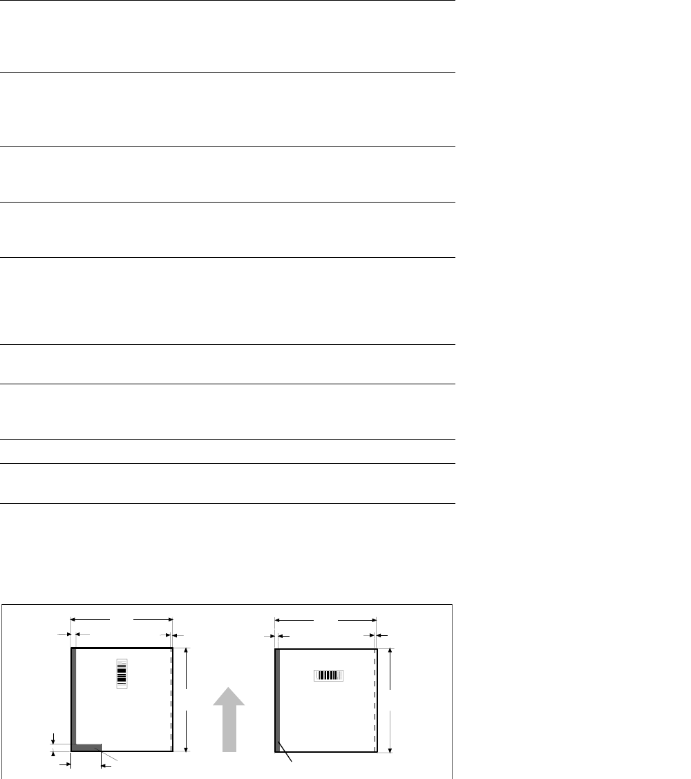
Restrictions for Bar Code Reading
of PCB Sizes 460 x 460 mm
2
Description
The SIPLACE PCB bar code scan-
ner supports the flexible produc-
tion of SMD products and en-
hances placement reliability. It
recognizes all code types in gen-
eral use for industrial applications.
The laser scanner reads the bar
code label on the top and/or bot-
tom of each PCB moving during
transport. On the basis of the bar
code information the line computer
automatically selects the correct
placement program from the pre-
viously prepared bar code assign-
ment list and sends it to the sta-
tion. This procedure is performed
in slack time while a PCB already
in the machine is being populated.
If a number of PCBs with the
same bar code are moved in one
after the other, the program is only
transferred the first time. The fol-
lowing preconditions apply for all
products which are to be manufac-
tured with the aid of the PCB bar
code:
§ identical component set-up at
the individual machines in the
line
§ all PCBs of same width.
The bar code filter can be utilized,
if only certain information con-
tained in the bar code is relevant.
PCB Conveyor:
PCB Bar Code for Production-Controlled Manufacturing (Option)
Technical Data
Bar-code-free PCB edge 3 mm on left and right parallel to PCB
transport direction (the additional restric-
tions shown in figure at the bottom apply
for scanning the bar code from above)
Label dimensions
Stroke width: W: 0.19 < W
≤ 0.3 mm
(corresponds to high + medium density)
Stroke length:
≥ 4 mm
a
Length of scanning window: ≤ 90 mm
Label alignment on PCB
b
Parallel or at right angles to the PCB
transport direction, preferably next to
fixed conveyor side
Recommended label colors
(contrast ratio > 70%
as per DIN 66236)
Color coding: black, dark green or dark
blue
Background: white, beige, yellow, orange
Code types Code 39, Code 128 / EAN 128,
Codabar, 2/5 IATA 2/5 industrial,
2/5 interleaved, UPC, EAN,
Pharma Code, EAN Addendum
(more upon request)
Complete bar code Max. 25 characters
Definition of a bar code filter possible
Safety of the laser scanner Laser diode 670 nm (red) / 1 mW
Laser protection class 2, degree of
protection IP65
Station and line software from Version 502.xxx
Scan-in/analysis time
Slack time (T
≤ 1 s), as parallel to the
placement of preceding PCB
a) This value can only be met if the bar code label on the PCB moves through the bar code scanner at
right angles to the machine’s direction of transport.
b) Depending on where the bar code label is located on the PCB, the position of the bar code scanner
can be easily adjusted in the input conveyor belt.
460 460
18.5 3
118
2
3
8
3
restricted
restricted
PCB
Transport
Direction
460
460
14
Description
Each side of the machine is
equipped with a changeover table.
As option, a MTC with a narrow
component table can be placed.
The component feeders are sta-
tionary during the placement proc-
ess, therefore it is possible to refill
components or splice tapes with-
out stopping the machine.
Either individual feeders or the en-
tire changeover table can be ex-
changed during changeover.
Use of component bar codes with
the aid of an optional component
bar code scanner guarantees the
correct assignment of the compo-
nent to the track.
To make full use of the advantages
of the component changeover ta-
ble, the entire set-up including the
check can also be conducted out-
side the machine at the optional
SIPLACE set-up station. The
changeover tables are equipped
with rollers and have an integrated
pneumatic lifting device, eliminat-
ing the need for a lifting device.
Exchanging the tables takes less
than 2 minutes per module.
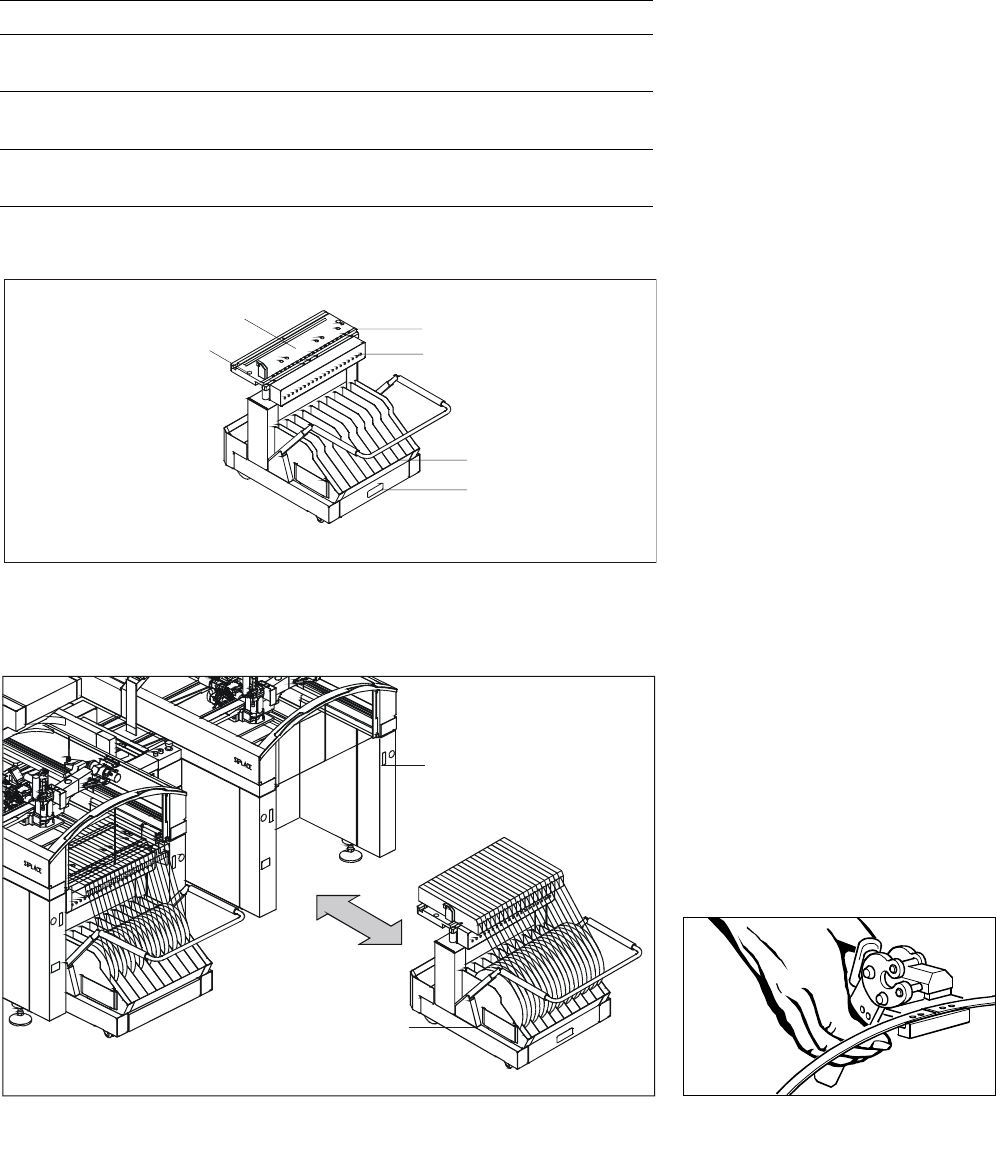
Component Supply:
Changeover Table
Technical Data
Insert (exchangeable) In all SIPLACE placement modules
Feeder locations 59 x 8 mm tracks per table,
118 x 8 mm tracks per machine
Feeder modules SIPLACE feeders for tapes,
stick magazines, Bulk Cases
Accessories Tape container, waste container,
empty tape cutter
Splicing Tool
Mobile Changeover Table
Feeder Table
Centering Position
Compressed Air
Feeder Connection
Reel Container
Reject Bin
Exchange of a Feeder Changeover Table
SIPLACE Station
Mobile
Changeover
Table
15
Description
The tape reels of the feeder mod-
ules are housed in the tape con-
tainer of the component change-
over table. A cutter automatically
chops up empty tape coming out
of the tape container.
Feeders used on SIPLACE are dis-
tinguished by a short cycle time
and a high-precision pick-up posi-
tion. Even product diversity and
small batch sizes can be handled
easily since the feeder set-up can
be changed quickly.
The increment of the tape cycle is
just as variable as the use of tape
materials. Thanks to the general
purpose tape feeding modules
which are equally suitable for pa-
per and blister tapes, a small range
of module types will be sufficient.
Activated by a signal from the
component table, the modules
control the entire feeder sequence
themselves, including the auto-
matic take-up of the strips.
The S Feeders series feature
shorter cycle times and they can
handle tapes with 2 mm grids
(8 mm S). 8 mm S and
12/16 mm S are equipped with
component cover.
The feeders can be used in other
SIPLACE machines as well.
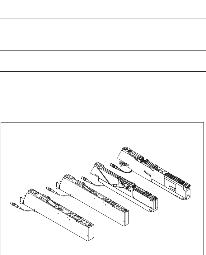
Component Supply:
Tape Feeder
Technical Data
Packaging Model Feeder
locations
Transport
distance
Max. Height
of component
Paper and
blister tapes
2 x 8 mm S
a
3 x 8 mm S
3 x 8 mm S
b
12/16 mm S
1
1
1
1
2 or 4 mm
2 or 4 mm
2 mm
4 - 12 mm
c
2.5 mm
2.5 mm
0.7 mm
14 mm
Blister tape 24/32 mm S 1.5 4 - 32 mm
c
14 mm
Tape reels Ø 7" to 19" (178 - 475 mm)
Feeder cycle S-feeder to 20 mm transport distance < 150 ms
a) Fiducial for recognition of position of feeders;
b) only for 0201 and 0402;
c) adjustable in increments of 4 mm.
Tape Feeder Modules S
24 / 32 mm S
12 / 16 mm S
3 x 8 mm S
2 x 8 mm S