西门子SIPLACE S25 HM-设备性能参数_EN - 第21页
19 Description The bar code scanner enables a quick and reli able che ck of com - ponent set-up and refill. The bar codes of the tracks and the lo aded components assigned to the track s (bar cod e labe ls on tap es, Bul…

18
Description
For high-volume production envi-
ronments requiring a wide range
of components, the use of a
SIPLACE Matrix Tray Changer is
highly recommended. The Matrix
Tray Changer is a high-speed, high-
capacity component delivery sys-
tem for SIPLACE S-25 HM.
The SIPLACE S-25 HM can be
equipped with up to two Matrix
Tray Changers, one on each side.
When high-volume production re-
quirements include larger or tray-
type components, the SIPLACE
MTC is the best solution.
Technology
TechnologyTechnology
Technology
§ Two independent tray carriers,
each with a JEDEC tray capacity
§ Each tray carrier is equipped
with a separate drive system
§ Set-up of the MTC is carried out
in accordance with the existing
SIPLACE optimization routine
§ The carrier is moved to the level
of the tray to be accessed, then
the tray is moved precisely to
the access area for pick-up by
the placement head
§ A separate control unit is con-
nected via interface cable
§ Operator information is available
via SIPLACE station computer
§ Easy handling due to removable
waffle pack carriers
§ Large storage capacity and
multiple component set-up
possibilities
§ When a waffle pack tray is de-
pleted, an alternate tray can be
accessed
§ Quick changeover of waffle
pack tray magazines containing
up to 10 waffle pack trays
§ External set-up is possible
Component Supply:
Matrix Tray Changer (Option)
Technical Data
Dimensions (L x W x H)
of Matrix Tray Changer (MTC)
of cassette
of Waffle Pack Tray Carrier (WPTC)
1.350 mm x 775 mm x 1.499 mm
354.1 mm x 154.8 mm x 131 mm
371 mm x 146 mm x 410.1 mm
Stroke vertical (between
WPTC 1 and WPTC 40)
502.5 mm
Stroke horizontal (between
reference and component position)
approx. 640 mm
Spacing between levels 11 mm
Spacing between cassettes 134.5 mm
Storage capacity 80 WPTCs
Changeover time (over 5 levels) < 2 sec
Weight of MTC
basic configuration
partially equipped
fully equipped
500 kg incl. cassettes and WPTCs
approx. 532 kg incl. components
600 kg incl. tapes and feeders
Weight of moving mass (equipped) 43.5 kg per tower
Weight of cassette approx.7.5 kg
Max. floor load fully equipped
per foot
per castor
2.78 kg/cm
2
4.01 kg/cm
2
Min. component size (L x W) 5 mm x 5 mm
Max. component height 13.5 mm
a
Max. noise generation
80 dB
A
a) When using components higher than 7.62 mm only every other tray can be used.
Electrical Connection (separate from machine power connection)
Frequency 50 Hz / 60 Hz
Phases 1; 3
Voltage 230/400 V or 110/208 V (USA)
Rated current 2.7 A or 4.2 A (USA)
Fusing 3 x 16 A
Rated current at max. load 2 A
19
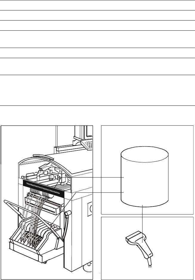
Description
The bar code scanner enables a
quick and reliable check of com-
ponent set-up and refill. The bar
codes of the tracks and the loaded
components assigned to the
tracks (bar code labels on tapes,
Bulk Cases, etc.) are read in with a
hand scanner. An audible and opti-
cal signal acknowledges a suc-
cessful reading operation. If the la-
bel is damaged the bar code can
be entered at the keyboard.
The allocation of the components
to their respective track is de-
scribed in the set-up data. An error
message is displayed if the data
received from the bar code scan-
ner does not conform to the set-up
data.
If the set-up check is switched on,
it becomes a mandatory step in
the set-up process. If it is
switched off the set-up check is
optional.
Component Supply:
Component Bar Code Scanner for Set-Up and Refill Check
(Option)
Technical Data
Connection Station computer
Data input Bar code scanner or keyboard
Number of characters Max. 40
Restrictions Bar codes beginning with number 1 or 2
and with less than 5 characters
Number of bar codes Max. 6 per component
Number of filters
to extract relevant data Max. 1 per bar code
Preset code types Code 39 (standard or full ASCII),
Code 2 from 5 interleaved and normal,
Code 128, UPC/EAN/JAN codes
(more on request)
Component
Control
Set-Up File
Track Bar Code
Component
Bar Code
Scanner
The scanner checks the corresponding track and
the components
20
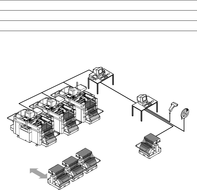
Description
The component changeover tables
can be set up and checked at an
external SIPLACE set-up station
quickly and without machine idle
time. The costs for production in-
volving a wide variety of compo-
nents are greatly reduced. During
the bar code check outside the
machine, 10 minutes of machine
standstill are eliminated per set-up
change. All current data from up to
4 lines are accessible over a link to
the line computer via a Local Area
Network (LAN).
In the case of the SIPLACE S-25
HM a component changeover ta-
ble is part of the standard equip-
ment. Additional changeover ta-
bles are required for optimal use
of the set-up station.
Component Supply:
SIPLACE External Set-Up Station (Option)
Technical Data
Operating system Windows NT 4.0
Set-up check Per bar code scanner
Component table change Time expanded: 2 min / table side
Example for SIPLACE Set-Up Station
Line
LAN
Line Computer
PC for External set-up
LAN Scanner
Serial Interface
Tape Reel
with
Bar Code
Mobile
Changeover
Table
Mobile
Changeover
Tables